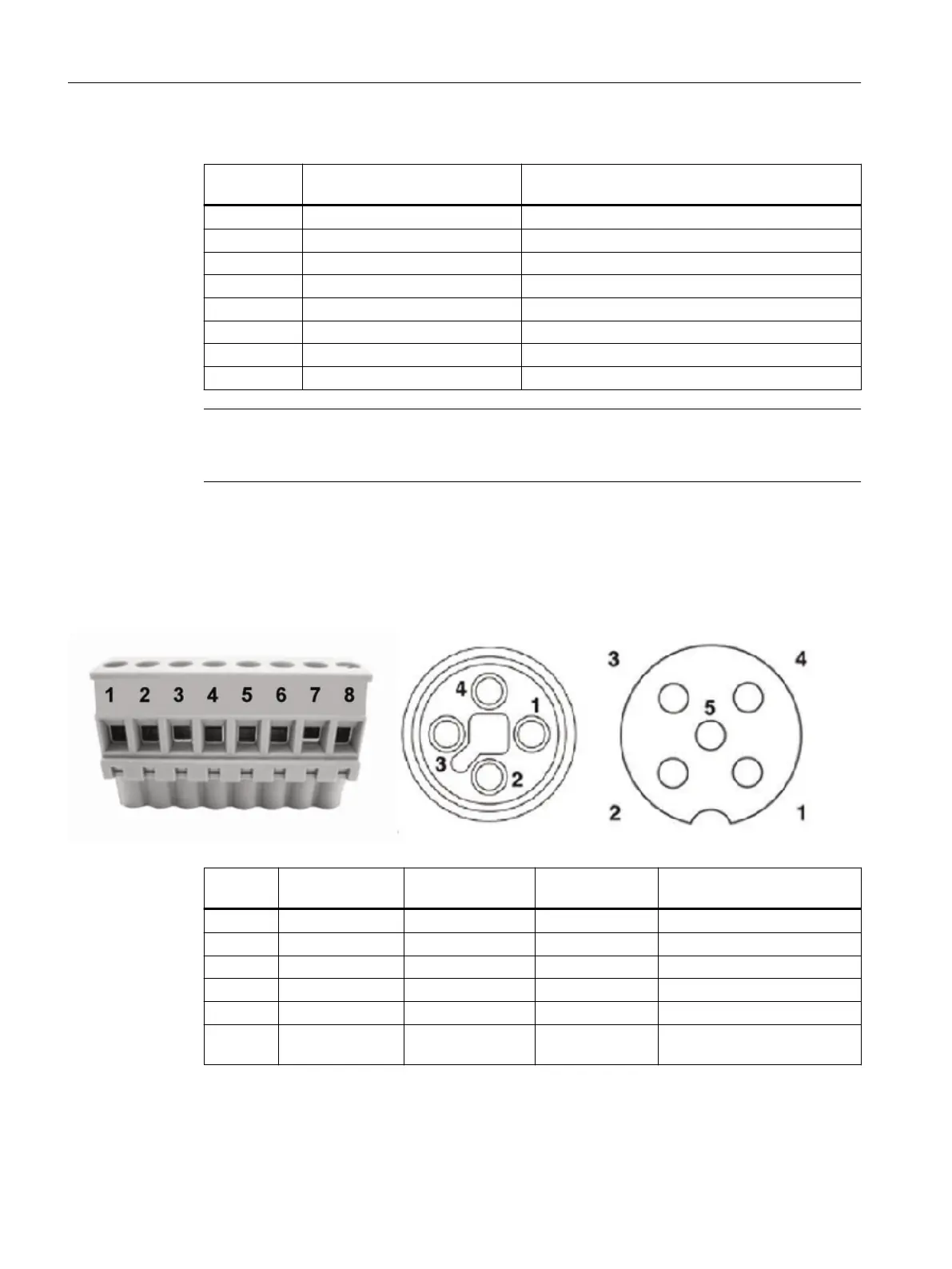
Table 6-1 Motor plug (slot X7)
Terminal
(X7)
Signal SIDOOR M3 / M4 / M5 wire color
1 +5 V Gray
2 Channel A Yellow
3 Channel B Green
4 Motor ID Brown
5 GND White
6 PE Yellow/green
7 Motor + Black 1
8 Motor - Black 2
Note
M3/M4/M5: The cables of these motors are permanently connected to the motor and have a
cable length of 1.5m.
You can nd additional information about connecting to the MDG-CABLE motor cable here:
(Page 231)
You can nd the technical specications of the various motor cables here: (Page 223)
,MFNNF9.PUPSTUFDLFSQPM1PXFS.PUPSTUFDLFSQPM&ODPEFS
Terminal
(X7)
Motor plug 4 pin.
(Power)
Motor plug 5 pin
(Encoder)
Signal SIDOOR MDG3 / MDG4 /
MDG5 wire color
1 1 +5 V Brown
2 2 Channel A White
3 4 Channel B Black
4 5 Motor ID Gray
5 3 GND Blue
6 Shield Shield Functional
ground
Yellow
Geared motors
6.3 Connecting terminals
ATD4xxW for industrial applications
210 System Manual, 06/2022, A5E51901827B AA

 Loading...


