Fail-Safe Modules
7.5 4/8 F-DI DC24V PROFIsafe Digital Electronic Module
ET 200S Distributed I/O System - Fail-Safe Modules
118 Installation and Operating Manual, 08/2008, A5E00103686-07
The wiring is carried out on the appropriate terminal module.
/ 0 9V 9V ', ', ', ', ', ', ', ',
/
0
6
6
6
6
PM-E
4/8 F-DI
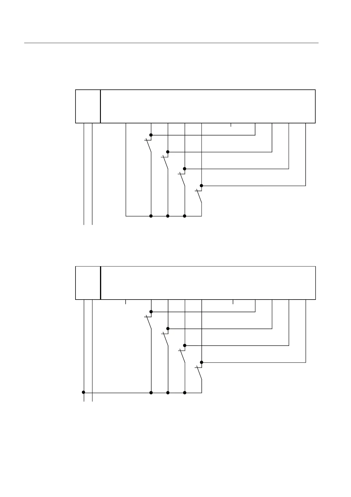
Figure 7-21 Wiring diagram EM 4/8 F-DI DC24V - one sensor connected via one channel to two
inputs, internal sensor supply
/ 0
/ 0
9V 9V',
6
6
6
6
', ', ', ', ', ', ',
PM-E
4/8 F-DI
Figure 7-22 Wiring diagram EM 4/8 F-DI DC24V - one sensor connected via one channel to two
inputs, external sensor supply

 Loading...


