Fail-Safe Modules
7.5 4/8 F-DI DC24V PROFIsafe Digital Electronic Module
ET 200S Distributed I/O System - Fail-Safe Modules
Installation and Operating Manual, 08/2008, A5E00103686-07
135
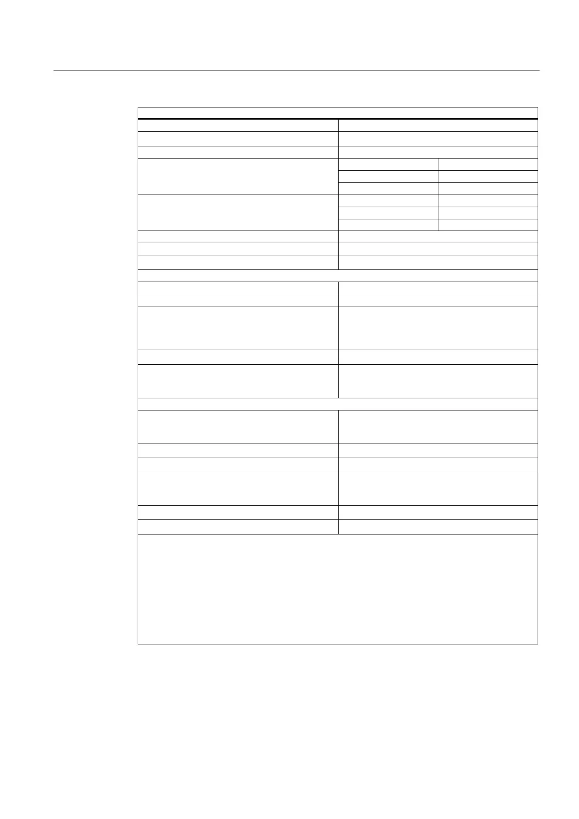
Technical Specifications
Input current
• For "1" signal
3.7 mA, typical
Input delay * Assignable (for all inputs together)
Typically 0.5 ms (0.3 ms to 0.7 ms)
Typically 3 ms (2.6 ms to 3.4 ms)
• For "0" after "1"
Typically 15 ms (13 ms to 17 ms)
Typically 0.5 ms (0.3 ms to 0.7 ms)
Typically 3 ms (2.6 ms to 3.4 ms)
• bei "1" nach "0"
Typically 15 ms (13 ms to 17 ms)
Input characteristic In accordance with IEC 61131-2 Type 1
Connection of 2-wire proximity switch (BERO) Not possible
• Permissible quiescent current
0.6 mA, maximum
Time, Frequency
Internal processing times See
"Response Times"
Acknowledgment time in safety mode
• Short-circuit test activated
With input delay of 0.5 ms:
With input delay of 3 ms:
With input delay of 15 ms:
Min. 4 ms / max. 7 ms
Min. 4 ms / max. 12 ms
Min. 4 ms / max. 9 ms
• Short-circuit test deactivated
Min. 4 ms / max. 6 ms
Minimum sensor signal duration See
"Minimum Duration of Sensor Signals to
Allow Correct Detection by the F-DI Module"
table in
"Wiring and Fitting Modules"
Protection against Overvoltage
Protection of power supply L+ from surge in
accordance with IEC 61000-4-5 with external
protection elements only
• Symmetrical (L+ to M)
1 kV; 1.2/50 μs
• Asymmetrical (L+ to PE, M to PE)
+2 kV; 1.2/50 μs
Protection of inputs and outputs from surge in
accordance with IEC 61000-4-5 with external
protection elements only
• Symmetrical (Vs, DI to M)
+1 kV; 1.2/50 μs
• Asymmetrical (Vs, DI to PE, M to PE)
+1 kV; 1.2/50 μs
*: With an input delay of 0.5 ms, shielded cables must be used for the digital inputs and the sensor
supply.
With 3 ms input delay, shielded cables must be used if there is a danger of overvoltage on the signal
lines (see section "Electromagnetic Compatibility") to prevent possible passivation of the fail-safe
digital inputs and the sensor power supply switching off. If unshielded signal lines are used, the safe
behavior of the process variables is ensured.
**: Operating below the permissible supply voltage is only permissible for the repair time. See chapter
"
Introduction (Page 61)."
***: For more information on the requirements for sensors and actuators, see "Wiring and Fitting
Modules".

 Loading...


