Fail-Safe Modules
7.7 4 F-DO DC24V/2A PROFIsafe digital electronic module
ET 200S Distributed I/O System - Fail-Safe Modules
Installation and Operating Manual, 08/2008, A5E00103686-07
169
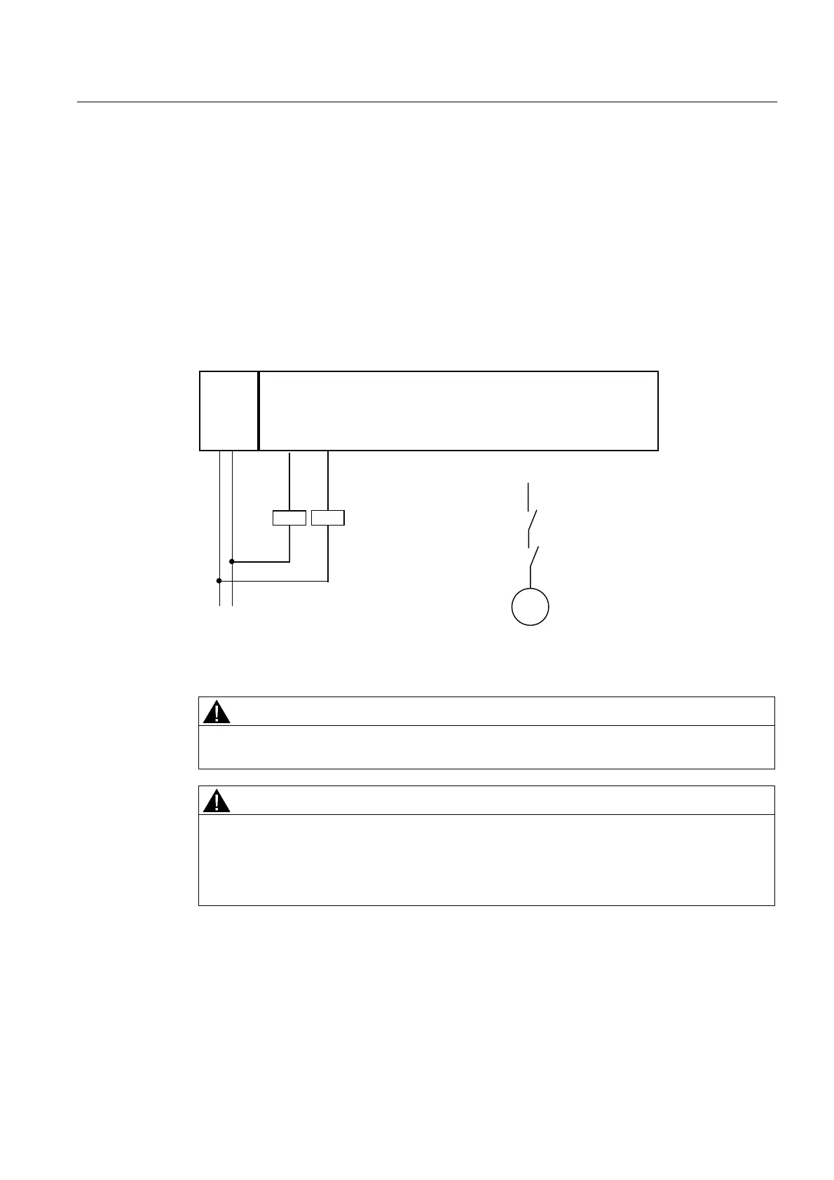
Application 2: Wiring loads to L+ and M at each digital output
You can connect two relays using one fail-safe digital output. The following conditions should
be kept in mind:
● L+ and M of the relays must be connected with L+ and M of the F-DO module (reference
potential must be equal).
● The normally open contacts of the two relays must be connected in series.
A connection to each of the four digital outputs is possible. The figure below shows an
example of the connection to DO0. This configuration achieves safety class SIL3/Category
4/PLe (process status readback required).
30(
/ 0
'2
0
'2
3
'2
0
'2
3
'2
0
'2
3
'2
0
'2
3
)'2
/ 0
.
. .
.
0
Figure 7-52 Wiring diagram for in each case 2 relays on 1 F-DO of the EM 4 F-DO DC24V/2A
PROFIsafe
WARNING
When connecting two relays on one digital output, (as shown in the figure above), the
errors "wire break" and "overload" are detected only at the P-switch (not at the M-switch).
WARNING
The controlled actuator can no longer be switched off should a cross circuit occur between
the P and M-switches of the output. To avoid cross circuits between the P and M-switches
of a fail-safe digital output, you should always wire the relay connection to the P and M-
switches separately, in order to prevent any cross circuits (for example with separately-
sheathed cables or using separate cable ducts).

 Loading...


