Fail-Safe Modules
7.8 1 F-RO DC24V/AC24..230V/5A Digital Electronic Module
ET 200S Distributed I/O System - Fail-Safe Modules
182 Installation and Operating Manual, 08/2008, A5E00103686-07
Wiring Diagram
30( (0)'2 (0)52
3
3
'2[
3
'2[
0
/ 0
,10 ,13
287 287 287 287
/ 0
. .
)
)
$&'& $&'&
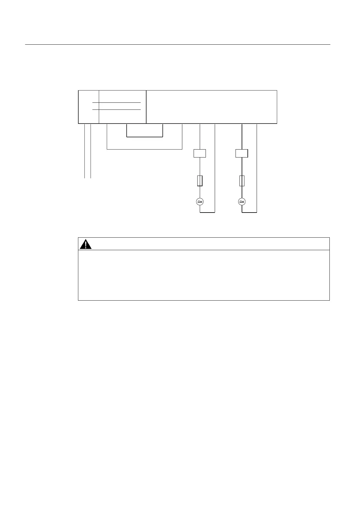
Figure 7-57 Wiring diagram of the EM 1 F-RO DC24V/AC24..230V/5A
WARNING
* Please always install an external fuse with the following properties in order to protect the
relay contacts against overload and short-circuits: Fusible cut-out, 6 A, operating class
gL/gG.
Note that for applications in accordance with EN 50156-1, the specified rated current of the
overcurrent protective device must be multiplied by the safety factor 0.6 to rule out the error
"non-opening of contact elements due to permanent contact welding".
Wiring the 24 VDC power supply
Apply the 24 VDC control voltage to IN P (terminals 3;7) and IN M (terminals 4;8). The 24
VDC line is usually connected via a PM-switching fail-safe output (e.g. EM 4 F-
DO DC24V/2A PROFIsafe). Wire the P-output of F-DO to IN P and the M-output to IN M of
the F-RO module.
You can also wire the circuit using a PP-switching fail-safe output. However, note that
external short-circuits to P at the P input cannot be controlled. In this case IN M would be
connected directly to the control voltage ground.

 Loading...


