Mounting and connecting the HMI device
3.3 Connecting the device
Comfort Panels
48 Operating Instructions, 07/2017, A5E36770603-AB
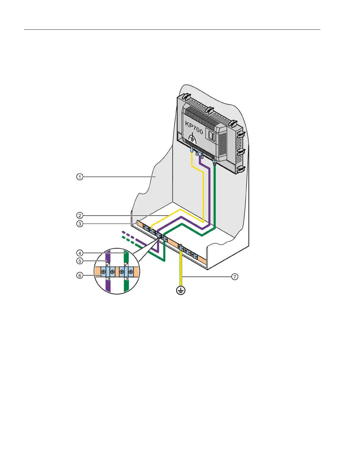
The following figure shows the connection of the equipotential bonding with KP700 Comfort
as an example and also applies to the other Comfort devices.
Equipotential bonding cable, 4 mm
2
Equipotential bonding rail
2

 Loading...

