EasyManuals Logo

Siemens SIMATIC NET S7-300 User Manual

Siemens SIMATIC NET S7-300
317 pages
To Next Page IconTo Next Page
To Previous Page IconTo Previous Page
Page #227 background imageLoading...
Page #227 background image
7 Programming FCs (Functions) and FBs for S7 Ethernet CPs
A-227
S7-CPs for Industrial Ethernet Configuring and Commissioning
Release 01/2007
C79000-G8976-C182-07
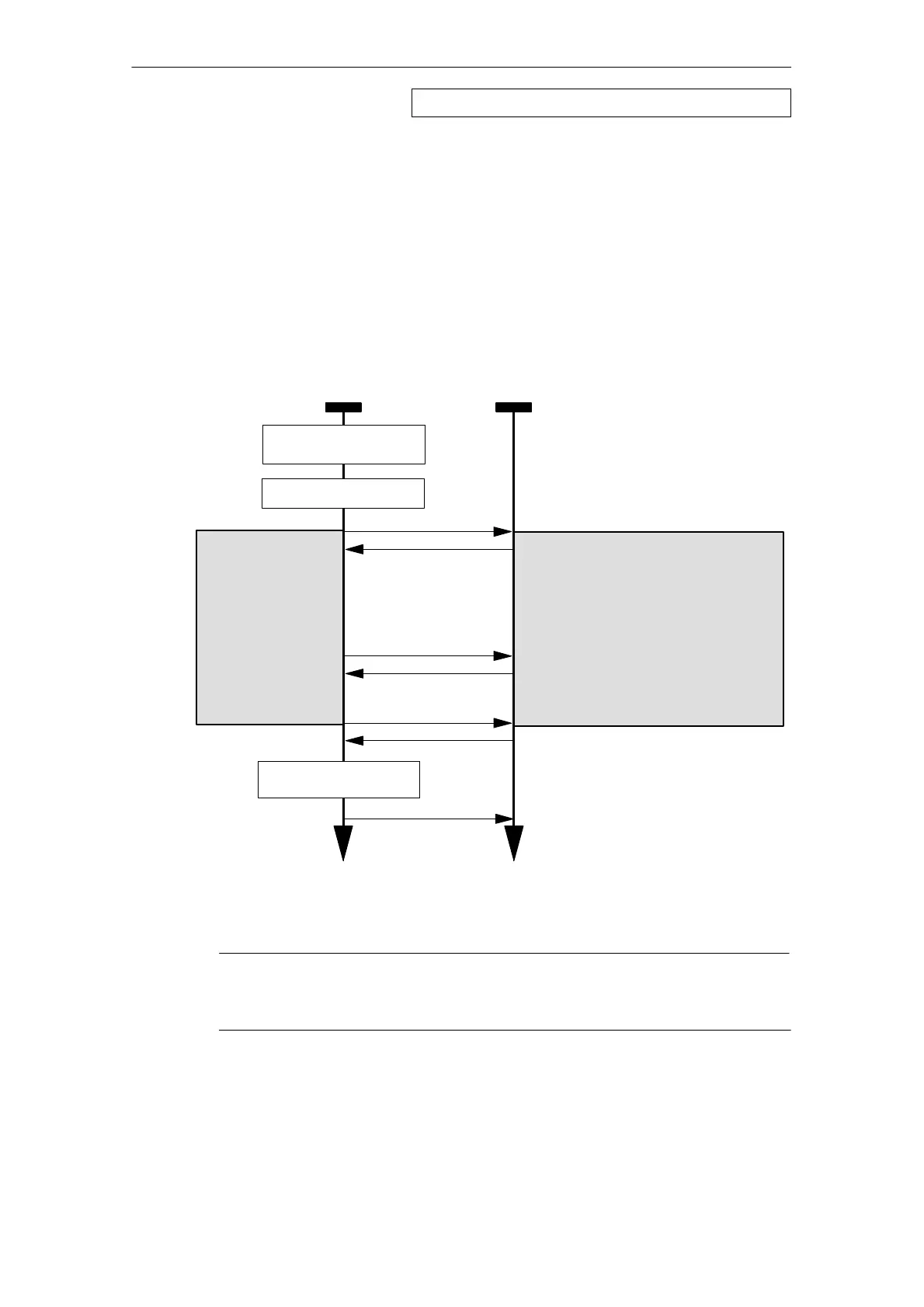
How It Works
The following diagram illustrates the normal sequence of connection configuration
triggered by an IP_CONFIG in the user program.
The job executes as soon as the parameter ACT is transferred with value 1.
Due to the segmented transfer of the CONF_DB, you will need to repeat the job
with ACT = 1 until completion of the job is indicated in the parameters DONE,
ERROR, and STATUS.
If you want to transfer a connection configuration again later, the parameter ACT
must first be transferred with value 0 in at least one further call.
User program
(CPU cycle)
Ethernet CP
Call IP_CONFIG
0, 0, Job active
1)
Call IP_CONFIG
Set ACT = 1
CP is supplied with system data
(including the IP address);
Connections are configured on the
CP.
Legend:
1)
Parameter transfer DONE, ERROR, STATUS
Time Time
Set ACT = 0
Call IP_CONFIG
0, 0, Job active
1)
CONF_DB is
transferred in
segments.
Supply CONF_DB with
data
Job completed without error
1)
Call IP_CONFIG
Notice
The data transferred with the configuration DB are stored in volatile memory on
the CP and must be downloaded to the CP again following a power down!
FB55 IP_CONFIG - continued

Table of Contents

Other manuals for Siemens SIMATIC NET S7-300

Questions and Answers:

Question and Answer IconNeed help?

Do you have a question about the Siemens SIMATIC NET S7-300 and is the answer not in the manual?

Siemens SIMATIC NET S7-300 Specifications

General IconGeneral
Product Type DesignationSIMATIC NET S7-300
MountingDIN rail mounting
Protection ClassIP20
CPU ModelsVarious models available (e.g., CPU 312, CPU 314)
Communication InterfacesMPI, PROFIBUS DP
Power Supply24 V DC power supply required. Different power supply modules available.
I/O ModulesDigital input modules, digital output modules, analog input modules, analog output modules
ProgrammingSTEP 7 software
Supply Voltage24V DC or 120/230V AC (depending on model)
Digital InputsAvailable via digital input modules
Digital OutputsAvailable via digital output modules
Analog InputsAvailable via analog input modules
Analog OutputsAvailable via analog output modules
Communication FunctionsMPI, PROFIBUS DP, Ethernet (depending on model)
ProtocolsMPI, PROFIBUS DP, TCP/IP (depending on model)
Operating Temperature0°C to 60°C
Storage Temperature70 °C
MemoryDepends on CPU model (e.g., 32 KB to 1.5 MB)

Related product manuals