7 Programming FCs (Functions) and FBs for S7 Ethernet CPs
A-228
S7-CPs for Industrial Ethernet Configuring and Commissioning
Release 01/2007
C79000-G8976-C182-07
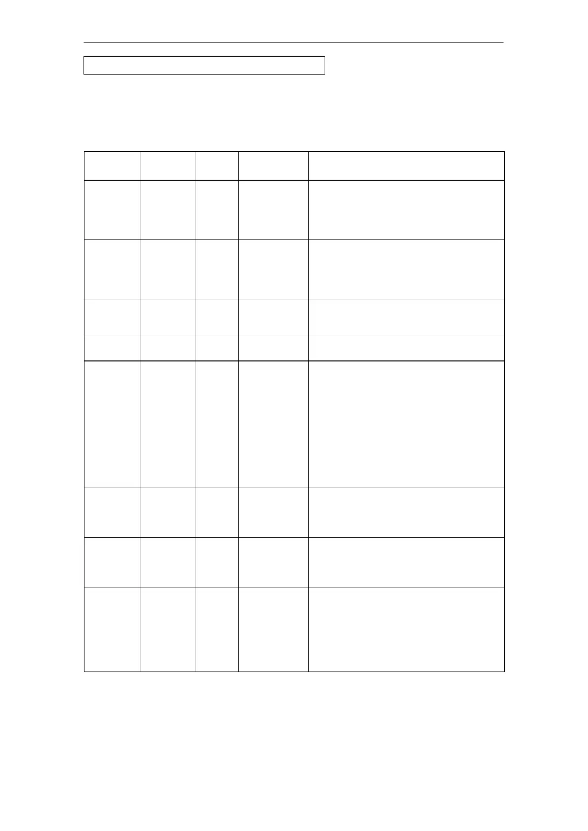
Explanation of the Formal Parameters
The following table explains the formal parameters for the call interface of the
IP_CONFIG function block :
Parameter Declaratio
n
Type Possible
Values
Remarks
ACT INPUT BOOL 0,1 When the FB is called with ACT = 1, the DBxx
is sent to the CP.
If the FB is called with ACT = 0, only the status
codes DONE, ERROR and STATUS are
updated.
LADDR INPUT WORD Module base address
When you configure the CP with STEP 7
hardware configuration, the module base
address is displayed in the configuration table.
Specify this address here.
CONF_DB INPUT ANY The parameter points to the start address of the
configuration data area in a data block (type:
byte).
LEN INPUT INT Length information in bytes for the configuration
data area.
DONE OUTPUT BOOL 0: -
1: new data
The parameter indicates whether the
configuration data area was completely
transferred.
Remember that it may be necessary to call the
FB several times depending on the size of the
configuration data area (in several cycles) until
the DONE parameter is set to 1 to signal
completion of the transfer.
For the meaning of this parameter in
conjunction with the ERROR and STATUS
parameters, refer to the following table.
ERROR OUTPUT BOOL 0: -
1: error
Error code
For the meaning of this parameter in
conjunction with the NDR and STATUS
parameters, refer to the following table.
STATUS OUTPUT WORD see following
table
Status code
For the meaning of this parameter in
conjunction with the NDR and ERROR
parameters, refer to the following table.
EXT_
STATUS
OUTPUT WORD If an error occurs in the execution of a job, the
parameter indicates which parameter was
detected as the cause of the error in the
configuration DB.
High byte: Index of the parameter field
Low byte: Index of the subfield within the
parameter field
FB55 IP_CONFIG - continued

 Loading...


