Preparing the 2000 mm mounting rail for installation
Proceed as follows to prepare the 2000mm mounting rail for installation:
1.
Cut the 2000mm mounting rail to the required length.
2.
Mark the holes. The necessary dimensions can be found in the table "Dimensions for the
drill holes":
–
Two drill holes at the beginning and end of the mounting rail
–
Additional drill holes at equal intervals of 500 mm maximum, along the identification
groove
3.
Drill the marked holes according to the selected type of fastening.
4.
Ensure that there are no burrs or shavings on the mounting rail.
NOTE
To ensure secure installation of the modules, make sure that the drill holes are centered in
the identification groove. Only use the maximum size of screws.
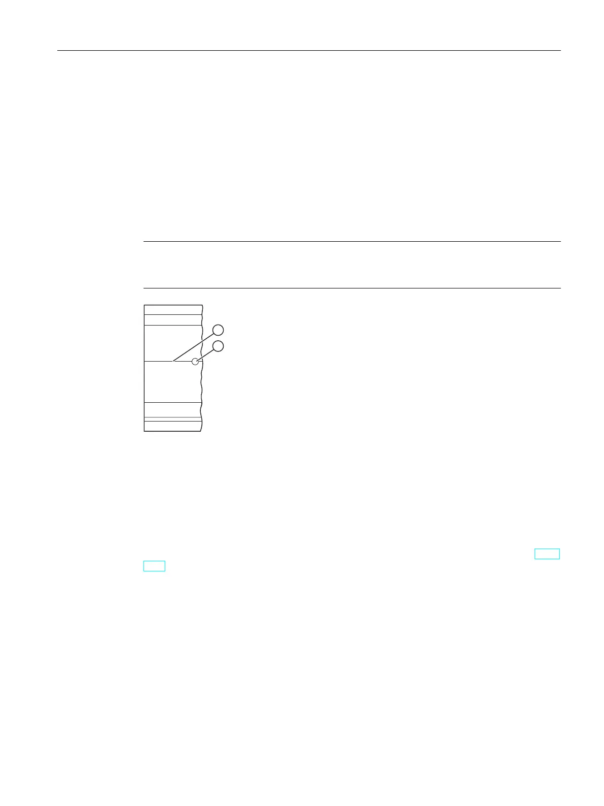
① Identification groove for additional drill holes
② Additional drill hole
Figure 6-2Preparing the 2000 mm mounting rail for installation
Installing the mounting rail
Install the mounting rails for the R/H-CPUs so that there is still sufficient space for installation
and heat dissipation. Please study the figure Minimum clearances in the control cabinet (Page
154).
Screw the rail onto the mounting surface.
Attaching the protective conductor
The mounting rails of the S7‑1500R/H redundant system must be connected to the protective
conductor system of the electrical system to ensure electrical safety.
Proceed as follows to connect the protective conductor:
1.
Strip the grounding conductor with a minimum diameter of 10mm
2
. Attach a ring
terminal for M6 bolts with the crimping pliers.
2.
Slide the enclosed bolt into the T profile groove.
157
Installation
6.2 Installing the mounting rail
S7-1500R/H redundant system
System Manual, 11/2022, A5E41814787-AD

 Loading...


