Detecting and Correcting Faults
6-7
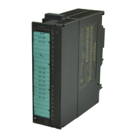
SM 335 – High-Speed Analog Input/Output Module for the SIMATIC S7-300
6ES7 335-7HG00-8BA1
6.4 SM 335 error tree
Tips for readers
Read the SM 335 error tree as follows: Bit 0 of module diagnostic byte 1 indicates
whether an error has occurred.
1. Check to see whether bit 0 in module diagnostic byte 1 is set.
2. If it is, check the bits to which the arrows going out from bit 0 of module diag-
nostic byte 1 point.
3. If a bit is set, follow the arrows going out from that bit and see which of those
bits are set, and so on.
4. See Table 6-2 for a description of the error associated with each bit.
Module diagnostic byte 1, bit 0
Module diagnostic byte 1, bit 17
Module diagnostic
byte 1, bit 7
Module diagnostic
byte 1, bit 2
Module diagnostic byte 1, bit 3
Module diagnostic
byte 3, bit 3
Module diagnostic
byte 4, bit 2
Module diagnostic
byte 4, bit 4
Module diagnostic byte 1, bit 4
Module diagnostic byte 3, bit 0
Module diagnostic
byte 1, bit 6
Channel-specific diagnostic
byte for analog input x, bit 0
Channel-specific
diagnostic byte for
analog output x, bit 0
Channel-specific diagnostic
byte for analog input x, bit 4
Channel-specific diagnostic
byte for analog input x, bit 1
Channel-specific diagnostic
byte for analog input x, bit 6
Channel-specific diagnostic
byte for analog input x, bit 7
Channel-specific diagnostic
byte for analog output x, bit 2
Fig. 6-1 SM 335 error tree
 Loading...
