Characteristics and Technical Specifications of the SM 335
1-3
SM 335 – High-Speed Analog Input/Output Module for the SIMATIC S7-300
6ES7 335-7HG00-8BA1
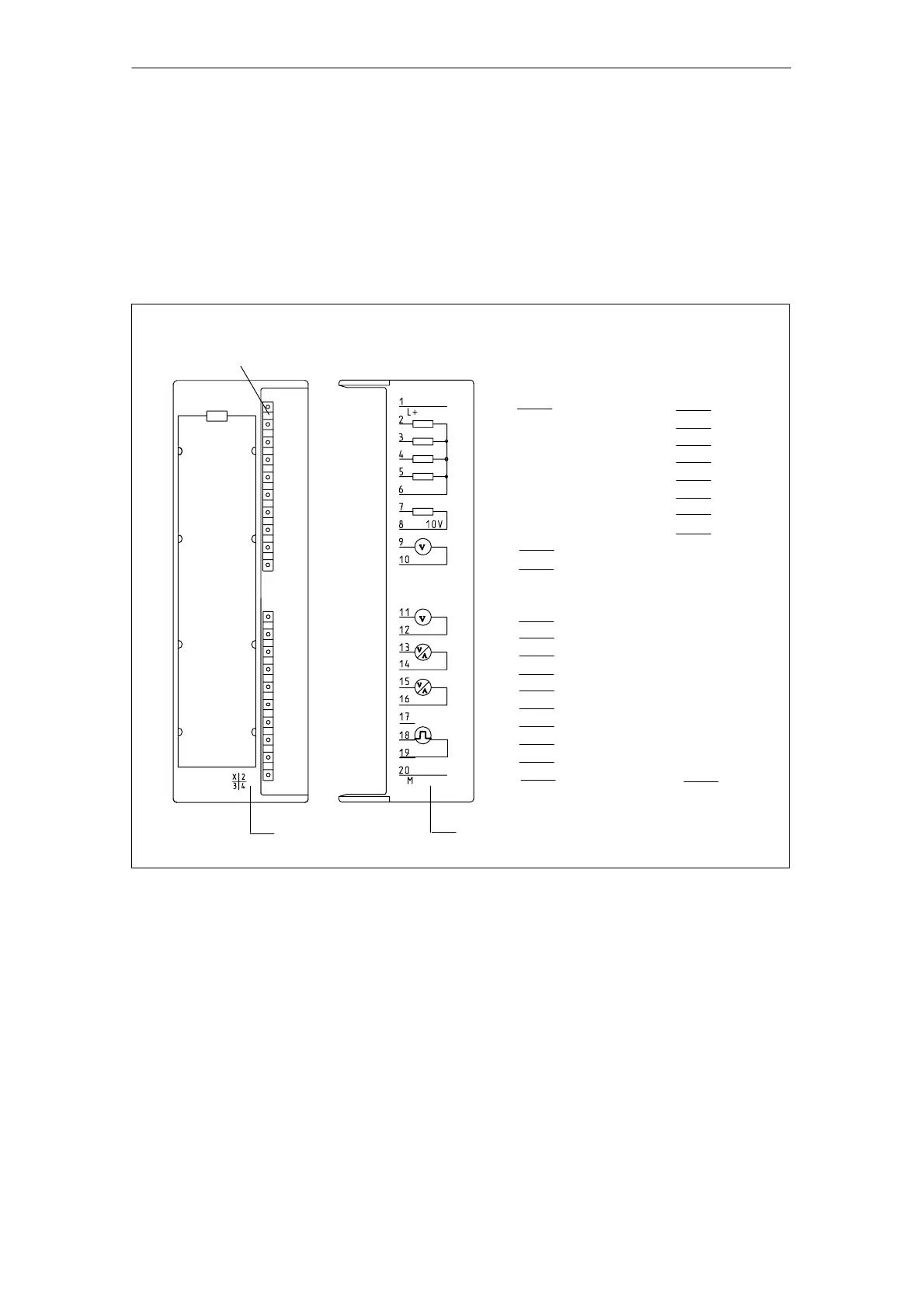
1.2 Terminal connection diagram for the SM 335
Terminal connection diagram
Figure 1-1 shows the terminal connections for the SM 335 analog input/output
module.
Terminal
Connection
Diagram
Fault LEDs – red
Analog inputs:
Voltage/
current measurement
L+
M
0+
M
0–
M
1+
M
1–
M
2+
M
2–
M
3+
M
3–
M
24 V
CH0
CH1
CH2
M
Analog outputs:
Voltage output
L+
QV
0
QV
1
QV
3
QV
2
M
ANA
M
24 V
CH0
CH1
CH2
CH3
M
CH3
Interval counter IZ
IZ
M
IZ
QV
Ref
M
ANA
10 V
SF
Sensor
power
supply
Revision level
Reserved
Fig. 1-1 Terminal connection diagram of the SM 335
Wiring
See Chapter 2 and to the SIMATIC S7-300, Hardware and Installation Manual for
information about how to wire inputs and outputs on the SM 335.
 Loading...