ix
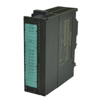
SM 335 – High-Speed Analog Input/Output Module for the SIMATIC S7-300
6ES7 335-7HG00-8BA1
Contents
1 Characteristics and Technical Specifications of the SM 335 1-1. . . . . . . . . . . . . . . .
1.1 Characteristics features of the SM 335 1-2. . . . . . . . . . . . . . . . . . . . . . . . . . . . .
1.2 Terminal connection diagram for the SM 335 1-3. . . . . . . . . . . . . . . . . . . . . . . .
1.3 Block diagram of the SM 335 1-5. . . . . . . . . . . . . . . . . . . . . . . . . . . . . . . . . . . . .
1.4 Setting the measuring range with the measuring range module 1-6. . . . . . . .
1.5 Technical specifications for the SM 335 1-7. . . . . . . . . . . . . . . . . . . . . . . . . . . . .
1.5.1 General technical specifications 1-7. . . . . . . . . . . . . . . . . . . . . . . . . . . . . . . . . . .
1.5.2 Technical specifications for the analog inputs 1-8. . . . . . . . . . . . . . . . . . . . . . . .
1.5.3 Technical specifications for the analog outputs 1-10. . . . . . . . . . . . . . . . . . . . . .
1.5.4 Technical specifications for the interval counter 1-11. . . . . . . . . . . . . . . . . . . . . .
1.6 SM 335 operating modes 1-13. . . . . . . . . . . . . . . . . . . . . . . . . . . . . . . . . . . . . . . . .
1.6.1 Free Cycle mode 1-13. . . . . . . . . . . . . . . . . . . . . . . . . . . . . . . . . . . . . . . . . . . . . . . .
1.6.2 Conditional Cycle mode 1-16. . . . . . . . . . . . . . . . . . . . . . . . . . . . . . . . . . . . . . . . . .
2 Connecting the Inputs and Outputs of the SM 335 2-1. . . . . . . . . . . . . . . . . . . . . . . .
2.1 Basic information about connecting the SM 335 2-2. . . . . . . . . . . . . . . . . . . . .
2.2 Connecting the analog inputs 2-3. . . . . . . . . . . . . . . . . . . . . . . . . . . . . . . . . . . . .
2.3 Connecting the analog outputs 2-5. . . . . . . . . . . . . . . . . . . . . . . . . . . . . . . . . . . .
2.4 Connecting the interval counter input 2-6. . . . . . . . . . . . . . . . . . . . . . . . . . . . . . .
2.5 Connecting the sensor power supply 2-7. . . . . . . . . . . . . . . . . . . . . . . . . . . . . . .
2.5.1 Correcting the sensor power supply 2-9. . . . . . . . . . . . . . . . . . . . . . . . . . . . . . . .
2.6 Interference suppression filter for 24 V supply voltage 2-10. . . . . . . . . . . . . . . .
3 Data Exchange with the SM 335 3-1. . . . . . . . . . . . . . . . . . . . . . . . . . . . . . . . . . . . . . . . .
3.1 Access via the I/O addresses 3-3. . . . . . . . . . . . . . . . . . . . . . . . . . . . . . . . . . . . .
3.1.1 Output values 3-3. . . . . . . . . . . . . . . . . . . . . . . . . . . . . . . . . . . . . . . . . . . . . . . . . . .
3.1.2 Output values 3-7. . . . . . . . . . . . . . . . . . . . . . . . . . . . . . . . . . . . . . . . . . . . . . . . . . .
3.1.3 Analog value representation for analog input channels 3-8. . . . . . . . . . . . . . . .
3.1.4 Analog value representation for analog output channels 3-10. . . . . . . . . . . . . .
3.2 Setting parameters via HW Config 3-11. . . . . . . . . . . . . . . . . . . . . . . . . . . . . . . . .
3.2.1 SM 335 default settings 3-12. . . . . . . . . . . . . . . . . . . . . . . . . . . . . . . . . . . . . . . . . .
3.2.2 SM 335 parameters assignable with HW Config 3-13. . . . . . . . . . . . . . . . . . . . .
3.3 Modifying SM 335 parameters with the help of system function 55 3-16. . . . .
3.3.1 SM 335 static parameters 3-17. . . . . . . . . . . . . . . . . . . . . . . . . . . . . . . . . . . . . . . .
3.3.2 SM 335 parameters in the Free Cycle and Conditional Cycle Modes 3-18. . . .
3.3.3 SM 335 parameter for “Comparator” mode 3-23. . . . . . . . . . . . . . . . . . . . . . . . . .
3.3.4 SM 335 parameters for “Measuring Only” special mode 3-27. . . . . . . . . . . . . . .
 Loading...
