Special SM 335 Operating Modes
5-13
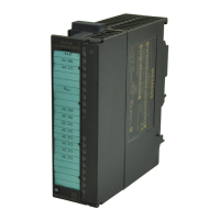
SM 335 – High-Speed Analog Input/Output Module for the SIMATIC S7-300
6ES7 335-7HG00-8BA1
Hardware interrupt (DS1, bit 12.4)
If bit 4 in the Comparator check byte is set to ’1’, the SM 335 generates a hard-
ware interrupt at the reversing point.
Analog output (DS1, bit 12.3 to 12.0)
Use bits 0 to 3 of the Comparator check byte (DS1, byte 12 – see Figure 5-8) to
specify the analog outputs, to which the analog values designated in DS1 (bytes 0
to 5 in Table 5-2) are to be forwarded.
• Bit i = ’1’: Specified value is output
• Bit i = 0: Old analog value is retained
You may set as many as three bits. The analog values are output until a new value
is forwarded to the output.
Comparator 1 and Comparator 2 (DS1, Bit 12.6 to 12.5)
Comparator bits 1 and 2 are used to activated Comparators 1 and 2
(see Table 5-3).
Table 5-3 Controlling the comparator via check bits 1 and 2
Bit 6
Bit 5 Comparator performance
1 1 Activate Comparators 1 and 2 in series
0 1 Activate Comparator 2
1 0 Activate Comparator 1
0 0 Exit “Comparator” mode immediately
Comparator 2 measured value
The measured value of Comparator 2 can be taken from the local data of the
OB 40. (Byte 10 and byte 11, see Subsection 3.4.1, Table 3-17)
 Loading...