Installation
2-12 SIMODRIVE base line A Start-Up
2.6.1.1. Pole pair numbers
The pole pair numbers of both the motor and resolver supplied to configured with Simodrive base
line A shall be 4. No change is allowed.
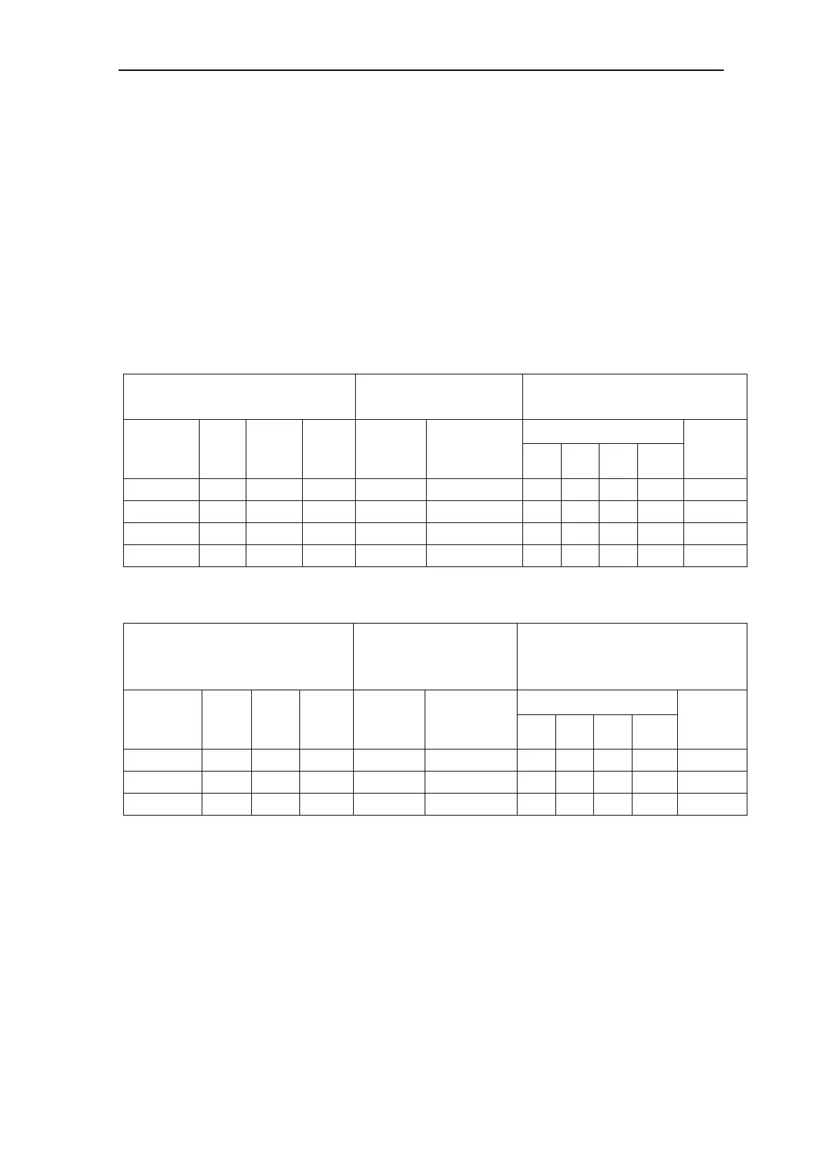
2.6.1.2. Current controller settings
DIL switch: S1 - used for selection of servomotors controlled by 1-axis module;
S2 – used for selection of servomotors controlled by 2-axes module;
Table 2-2 Adaptation table for Simodrive base line A (1-axis module)
Servomotor
Curr. act. value norm.
Axis 1: S1
Current controller gain K
p
(I)
Axis 1: S1
Contacts
1)
1FK
M
0
[Nm]
100K
I
0
[A]
100K
N
rated
[RPM]
Contact
1+2
I
max
[%]
3+7 4+8 5+9 6+10
K
p
(I)
7060-5AF 6.0 4.5 3000 x 70 x o o x 9.5
7063-5AF 11.0 8.0 3000 o 100 o x x o 7.5
7080-5AF 8.0 4.8 3000 x 70 x o o x 9.5
7083-5AF 16.0 10.4 3000 o 100 x o x o 6.0
Table 2-3 Adaptation table for Simodrive base line A (2-axes module)
Servomotor
Curr. act. value norm.
Axis 1: S1
Axis 2: S2
Current controller gain K
p
(I)
Axis 1: S1
Axis 2: S2
Contacts
1)
1FK
M
0
[Nm]
100K
I
0
[A]
100K
N
rated
[RPM]
Contact
1+2
I
max
[%]
3+7 4+8 5+9 6+10
K
p
(I)
7042-5AF 3.0 2.2 3000 x 70 o x o x 10.5
7060-5AF 6.0 4.5 3000 o 100 o x x o 7.5
7080-5AF 8.0 4.8 3000 o 100 o x x o 7.5
1)
Definition: o =Contact in the basic OFF setting x = Contact in the basic ON setting