EasyManuals Logo
Home>Siemens>Controller>SIMODRIVE base line A

Siemens SIMODRIVE base line A User Manual

Siemens SIMODRIVE base line A
52 pages
To Next Page IconTo Next Page
To Previous Page IconTo Previous Page
Page #19 background imageLoading...
Page #19 background image
Installation
SIMODRIVE base line A Start-Up 2-7
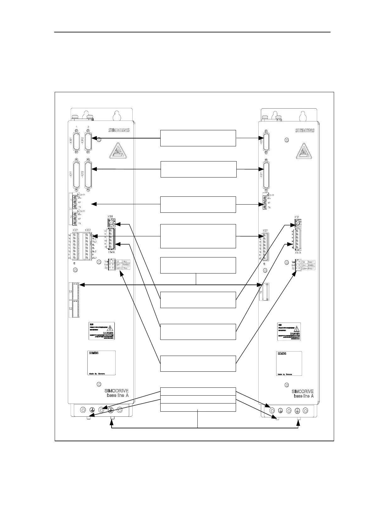
2.4. Interfaces and cabling
General Position of the interfaces and elements on the front panel are shown in the
following figure.
Position feedback interface
X391+X392(2-axes)/X391(1-axis)
Encoder interface
X311+X312(2-axes)/X311(1-axis)
Adjustment potentiometer
Drift, tachometer, Kp, Tn
Speed setpoint &
controller enable interface
X321+X322(2-axes)/X321(1-axis)
Grounding terminal
X131
Enable interface terminal
X141A
LED lights
PE1/PE2/PE
A1(U2,V2,W2)/A2(U2,V2,W2)
X1(U1,V1,W1)
DIL switch
S1+S2(2-axes)/S1(1-axis)
Fig.2-4 Front panel of SIMODRIVE base line A (2-axes module left, 1-axis module right)

Questions and Answers:

Question and Answer IconNeed help?

Do you have a question about the Siemens SIMODRIVE base line A and is the answer not in the manual?

Siemens SIMODRIVE base line A Specifications

General IconGeneral
BrandSiemens
ModelSIMODRIVE base line A
CategoryController
LanguageEnglish

Related product manuals