Technical description
3-2 SIMODRIVE base line A Start-Up
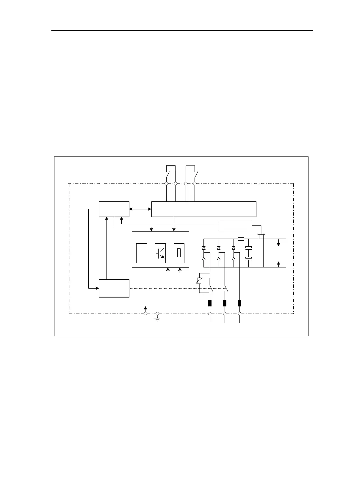
3.2. Infeed module
General SIMODRIVE base line A is connected to the power supply via the infeed
modules. The infeed module generates the DC voltage 600V from the
line supply. And the PWM DC link voltage is provided for the stator
windings in the motor. The resolver built-in the motor switches over the
current to appropriate phase.
The infeed module is designed with a permissible dynamic overloading
200% for a short time. The design of heatsink overtemperature and I
2
t
monitoring protect the power part from over heating.
Control process
Electronics power
supply
Monitoring
Pre-charge
contactor
DC link
monitoring
P600
M600
Monitoring
P600 M600
Pulse resistor controller
64 9 9 63
L1 L2 L3
U1 V1 W1
X131
PE
Drive
enable
Pulse
enable
3AC 400/415V
Fig.3-2 Control process in infeed module