Connecting
5.1 Wiring
SIMOTION C
Operating Instructions, 02/2012
117
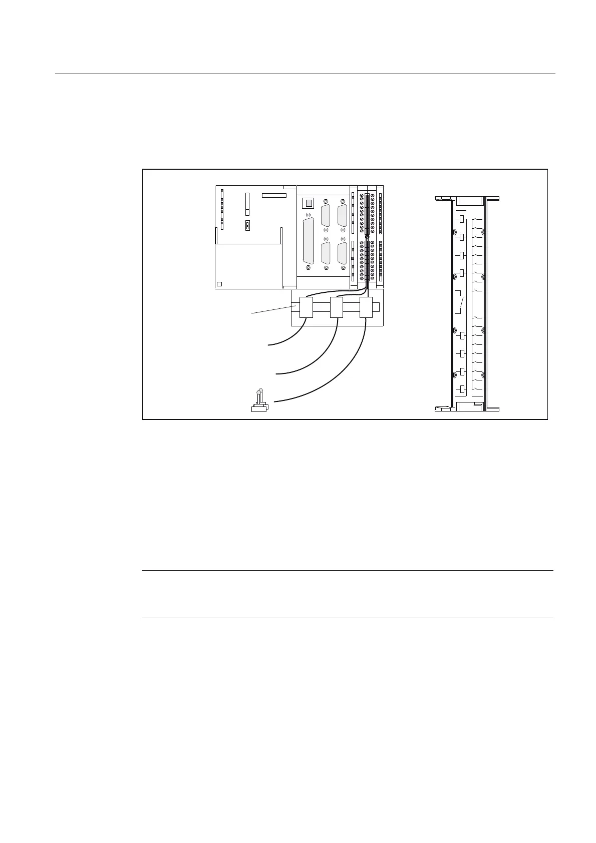
5.1.7 Wiring the front connector
The following figure shows how the cables are routed to the front connector and how to
suppress line interference through the use of the shield connecting element.
3UREH
5($'<FRQWDFW
6KLHOGFRQQHFWLQJHOHPHQW
/DEHOLQJRILQQHUGRRU
'LJLWDOLQSXWVRXWSXWV
;
0
/
0
&&
;
; ;
;;
6,(0(16
;
&
05(6
6723
581
Figure 5-16 Wiring the front connector
Connecting cables
Flexible cable, cross-section 0.25 to 1.5 mm
2
Ferrules are not required.
You can use ferrules without an insulating collar in accordance with DIN 46228, Form A long
version.
You can connect two cables of 0.25 to 0.75 mm
2
each in one ferrule.
Note
To achieve optimum interference suppression, a shielded cable must be used for connection
of measuring inputs or external zero mark.
Required Tools
3.5-mm screwdriver or power screwdriver