Interfaces
3.4 Encoder interface (HTL/TTL/SSI)
SIMOTION D410-2
Manual, 02/2012
39
Interface assignment
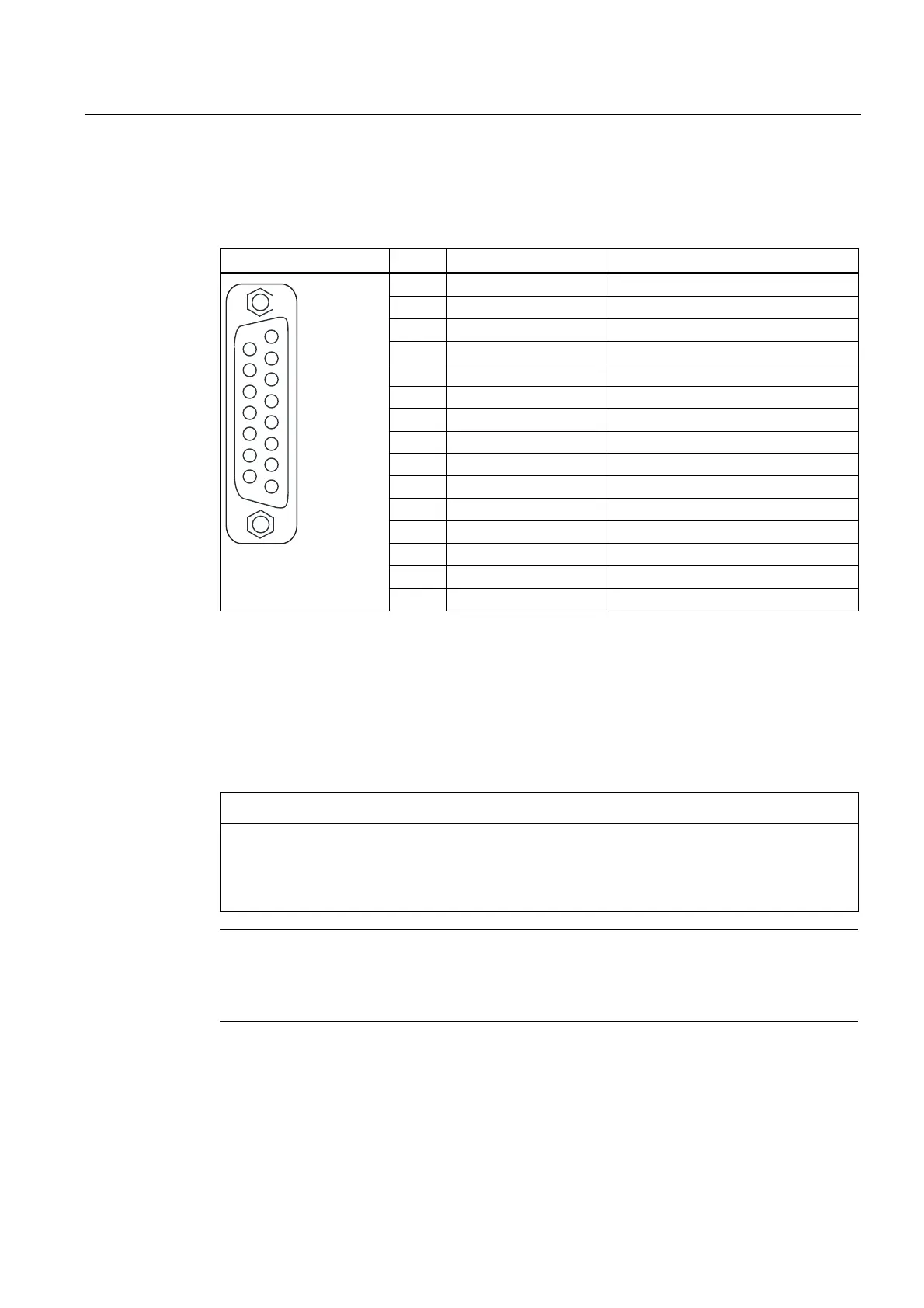
Table 3- 10 Interface assignment X23
Representation Pin Name Description
1 +Temp KTY or PTC input
2 SSI_CLK SSI clock positive
3 SSI_XCLK SSI clock negative
4 P_Encoder 5 V / 24 V Encoder power supply
5 P_Encoder 5 V / 24 V Encoder power supply
6 P_Sense Sense input encoder power supply
7 G_Encoder (G) Ground for sensor power supply
8 -Temp (G) Ground for KTY or PTC
9 G_Sense (G) Ground sense input
10 RP R track positive
11 RN R track negative
12 BN B track negative
13 BP B track positive
14 AN_SSI_XDAT A track negative / SSI data negative
15 AP_SSI_DAT A track positive / SSI data positive
For Pin 1 / Pin 8: The associated temperature channel (T1) can be assigned parameters as an
individual channel or together in combination with the second temperature channel (T2) at
interface X120.
(For parameterization, refer to the
SINAMICS S120
Commissioning Manual).
For Pin 6 / Pin 9: At an encoder supply of 5 V, the voltage drops on the encoder supply cables are
recorded and compensated by means of the sense cables. For this purpose, the sensor supply is
corrected on the SIMOTION D410-2.
NOTICE
The KTY temperature sensor must be connected with the correct polarity. A sensor
connected with the incorrect polarity cannot detect the motor overheating. For more
information on the temperature sensors and how to use them, refer to the
SINAMICS S120
Commissioning Manual, chapter entitled Temperature sensors for SINAMICS components.
Note
There are two ways of connecting the temperature sensor:
1. Via X120, terminal 1 and 2
2. Via X23, pin 1 and 8