Interfaces
3.4 Encoder interface (HTL/TTL/SSI)
SIMOTION D410-2
40 Manual, 02/2012
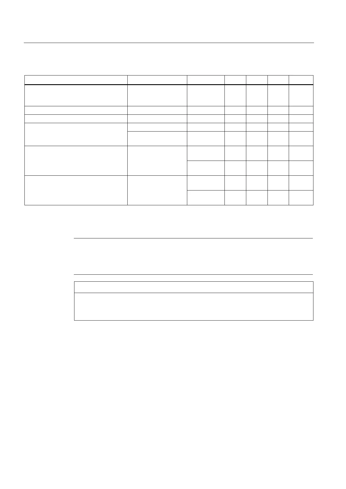
Table 3- 11 Specification of measuring systems that can be connected
Parameter Designation Threshold Min. Type Max. Unit
Permissible signal level in the bipolar
mode (parameter p0405.1=1);
(TTL, SSI, HTL bipolar at X23)
1), 2)
U
diff
2,0 V
CC
V
Permissible signal frequency f
S
- 500 kHz
Required edge clearance t
min
100 - ns
Length ¼ · T
s
¾ · T
s
Permissible zero pulse (with T
s
= 1/f
s
)
Center of the pulse
position
50 135 220 Degrees
High
(p0405.4=1)
8,4 10,6 13,1 V Switching threshold in the unipolar mode
(parameter p0405.0=0) and signals
AN_SSI_XDAT, BN, RN at X23 connected
to M_Encoder
U
(Schalt)
Low
(p0405.4=0)
3,5 4,8 6,3 V
High
(p0405.4=1)
9 11,3 13,8 V Switching threshold in the unipolar mode
(parameter p0405.0=0) and signals
AN_SSI_XDAT, BN, RN not connected to
X23
U
(Schalt)
Low
(p0405.4=0)
5,9 7,9 10,2 V
1)
Other signal levels according to the RS422 specification.
2)
The absolute level of the individual signals varies between 0 V and VCC of the measuring system.
Note
We recommend that bipolar encoders are used.
When using unipolar encoders, the unused negative track signals can either be connected or
connected to ground. This results in different switching thresholds.
NOTICE
Prefabricated cable for 5 V - TTL encoder
If a 5 V - TTL encoder (6FX encoder) is used, the connecting cable 6FX8002-2CR00-...
must be used.
 Loading...


