Interfaces
3.5 Digital I/Os / temperature sensor / analog input
SIMOTION D410-2
44 Manual, 02/2012
The maximum length of the temperature sensor cable is 300 m. The cables must be
shielded. For cable lengths >100 m, cables with a cross-section of ≥1 mm² must be used.
DANGER
Risk of electric shock!
Only temperature sensors that meet the electrical separation specifications contained in
EN 61800-5-1 may be connected to terminals "+Temp" and "-Temp". If safe electrical
separation cannot be guaranteed (for linear motors or third-party motors, for example), a
Sensor Module External (SME120 or SME125) or Terminal Module TM120 must be used.
If these instructions are not observed, there is a risk of electric shock!
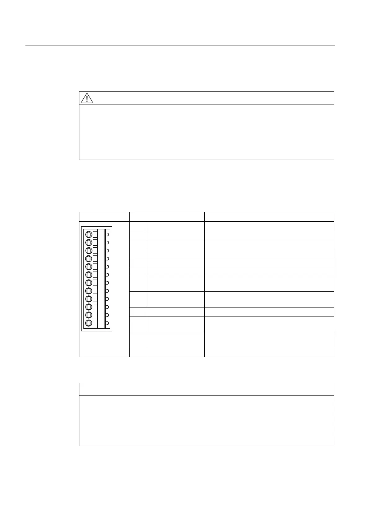
X121
Table 3- 15 Interface assignment X121
Representation Pin Designation Information
1 DI 0 Isolated digital input 0
2 DI 1 Isolated digital input 1
3 DI 2 Isolated digital input 2
4 DI 3 Isolated digital input 3
5 M2 Ground reference for DI 0 - DI 3
6 M Ground reference of the electronics
1)
7 DI/DO 8 High-speed digital I/O 8,
not isolated
8 DI/DO 9 High-speed digital I/O 9,
not isolated
9 M Ground reference of the electronics
1)
10 DI/DO 10 High-speed digital I/O 10,
not isolated
11 DI/DO 11 High-speed digital I/O 11,
not isolated
12 M Ground reference of the electronics
1)
1)
Reference potential for the digital I/Os and analog input
NOTICE
An open input is interpreted as "low".
The use of the digital inputs (DI 0 ... DI 3) requires terminal M2 be connected. This is
achieved by:
• Also routing the ground reference of the digital inputs, or
• A jumper to terminal M. This removes the electrical isolation for these digital inputs.
 Loading...


