Interfaces
3.5 Digital I/Os / temperature sensor / analog input
SIMOTION D410-2
Manual, 02/2012
45
X130
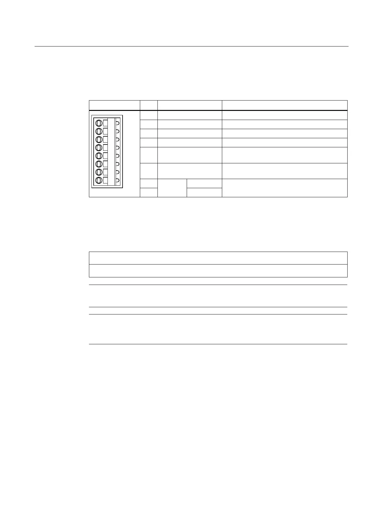
Table 3- 16 X130 interface assignment
Representation Pin Designation Information
1 DI 22+ Isolated digital input 22
2 DI 22-
2)
Reference potential for DI 22+
3 M2 Ground reference for DI 0 - DI 3
4 M Ground reference of the electronics
1)
5 M1 Reference potential for the fail-safe digital I/Os
(or for DI 16, DI 18, DI 20 and DO 16)
6 24 V1 Power supply for F-DI 0, F-DI 1, F-DI 2 and F-
DO
7 DO 16+
3)
8
F-DO 0
4)
DO 16-
Fail-safe digital output 0 or digital output 16
1)
Reference potential for the digital I/Os and analog input
2)
Reference potential for DI 20+
3)
The proper functioning of the DO 16 requires that the terminals 5/6 be connected.
4)
F-DO 0 for Safety Integrated extended functions
NOTICE
An open input is interpreted as "low".
Note
If M1 or M2 is connected with M, the electrical isolation no longer exists.
Note
The fail-safe digital output (DO 16+, DO 16-) switches off retentively in the event of a short-
circuit.
 Loading...


