Interfaces
3.5 Digital I/Os / temperature sensor / analog input
SIMOTION D410-2
46 Manual, 02/2012
X131
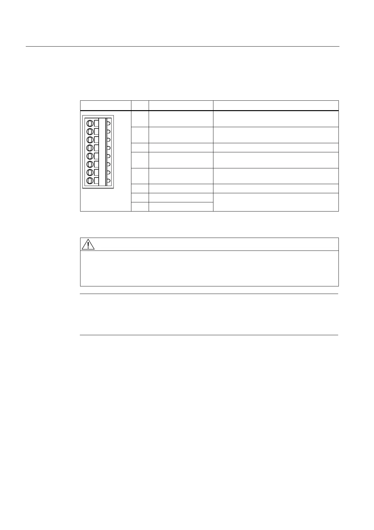
Table 3- 17 X131 interface assignment
Representation Pin Designation Information
1 DI/DO 12 High-speed digital I/O 12,
not isolated
2 DI/DO 13 High-speed digital I/O 13,
not isolated
3 M Ground reference of the electronics
1)
4 DI/DO 14 High-speed digital I/O 14,
not isolated
5 DI/DO 15 High-speed digital I/O 15,
not isolated
6 M Ground reference of the electronics
1)
7 AI 0+
8 AI 0-
Analog voltage or current input
1)
Reference potential for the digital I/Os and analog input
CAUTION
The common mode range may not be violated. This means that the analog differential
voltage signals can have a maximum offset voltage of ±12 V with respect to the reference
potential. If the range is infringed, incorrect results may occur during analog/digital
conversion.
Note
A 24 V supply voltage must be connected to terminal X124 for the digital outputs to be used.
If momentary interruptions in the voltage occur in the 24 V supply, the digital outputs are
deactivated until the interruption has been rectified.
If a digital output is parameterized and the external 24 V power supply is not connected (or
the level is too low), the A03506 warning will be issued. This warning can also parameterized
as a fault.
See also
Connection examples (Page 49)
 Loading...


