X120
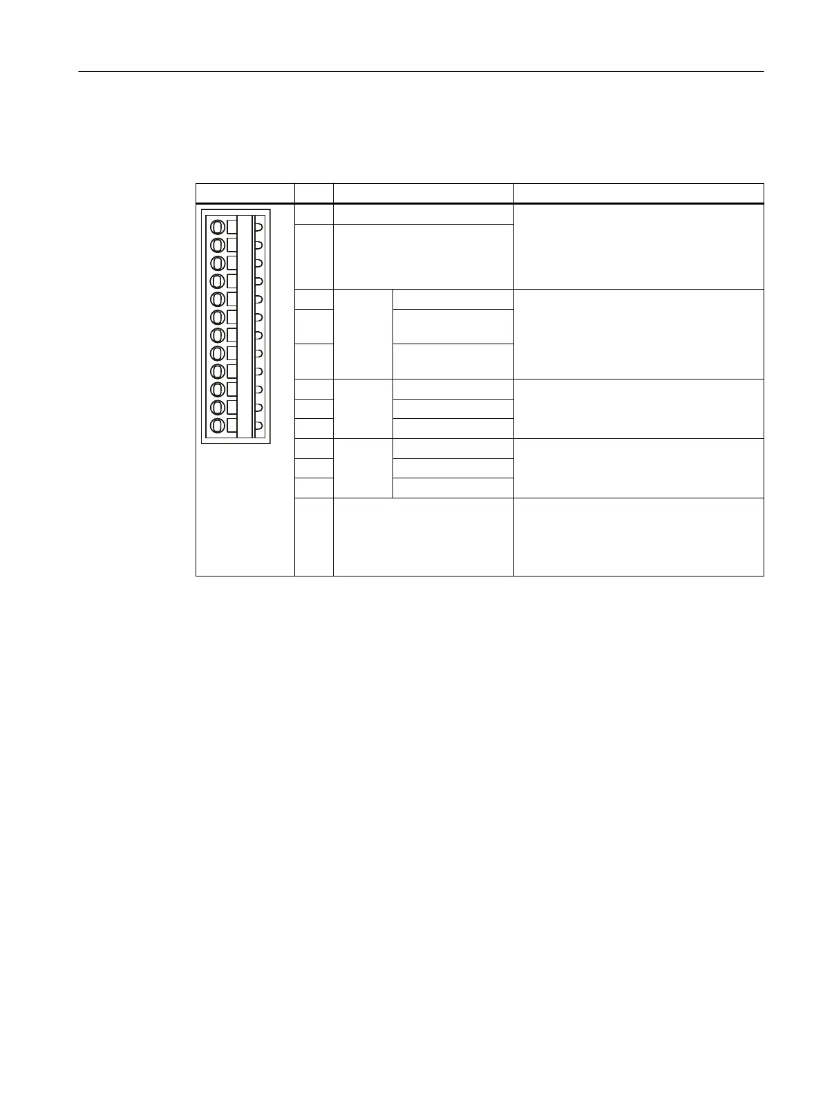
Table 4-17 Interface assignment X120
Representation Pin Designation Notes
1 +Temp Motor temperature sensor input.
Temperature sensors: KTY84–1C130 /
PT1000 / PTC
Measuring current via temperature sensor
connection: 2 mA
2 -Temp
3 F-DI 0
2)
DI 16 Fail-safe digital input 0 or digital inputs 16
and 17
EP function (Enable Pulses) when using Safe‐
ty Integrated Basic Functions via terminal
4 DI 17+ / EP +24 V3
(Enable Pulses)
5 DI 17- / EP M3 (Ena‐
ble Pulses)
1)
6 F-DI 1
2)
DI 18 Fail-safe digital input 1 or digital inputs 18
and 19
7 DI 19+
8 DI 19-
1)
9 F-DI 2
2)
DI 20 Fail-safe digital input 2 or digital inputs 20
and 21
10 DI 21+
11 DI 21-
1)
12 M1 Reference potential for:
• DI 16, DI 18 and DI 20 (or F-DI 0 to F-DI 2;
rst shutdown path)
• DO 16+ (or F‑DO 0)
1)
Reference potential for DI 17+ / DI 19+ / DI 21+ (or F-DI 0 to F-DI 2; second shutdown path)
2)
Functionality depends on the parameterized Safety Integrated functions.
Interfaces
4.6 Digital I/Os / temperature sensor / analog input
SIMOTION D410-2
Equipment Manual, 07/2021, A5E33446720B 59

 Loading...


