Start-Up 09.02
4-56 Siemens AG 6SE7087-6AK85-1AA0
Rectifier/Regenerating Unit Operating Instructions
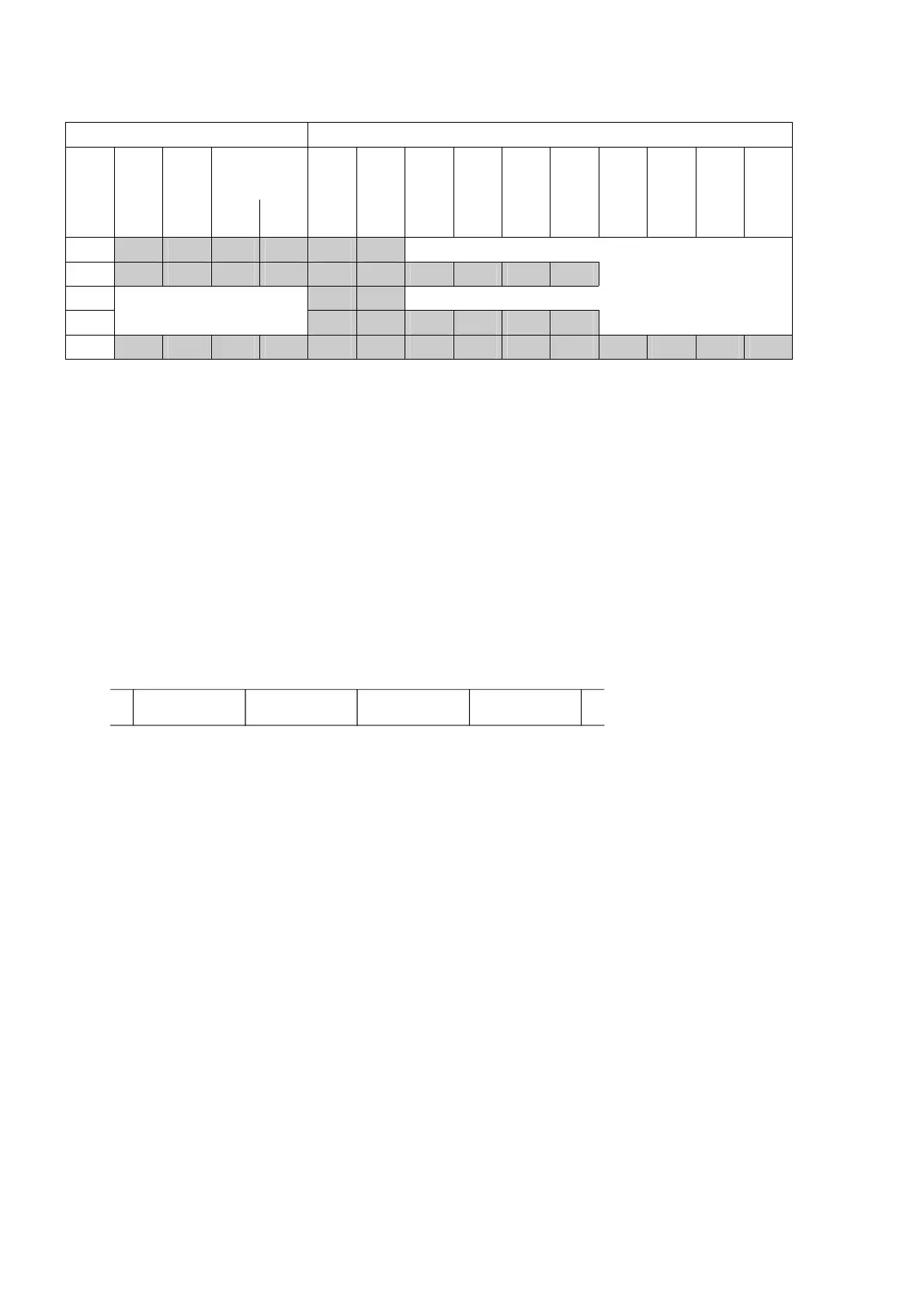
A total of five PPO types are defined:
PKW section PZD section
PKE IND PWE PZD1
STW1
ZSW1
PZD2
HSW
HIW
PZD3 PZD4 PZD5 PZD6 PZD7 PZD8 PZD9 PZD
10
1
st
word
2
nd
word
3
rd
word
4
th
word
1
st
word
2
nd
word
3
rd
word
4
th
word
5
th
word
6
th
word
7
th
word
8
th
word
9
th
word
10
th
word
PPO1
PPO2
PPO3
PPO4
PPO5
PKW: Parameter ID value IND: Index ZSW Status word
PZD: Process data PWE: Parameter value HSW: Main setpoint
PKE: Parameter identifier STW: Control word ISW: Main actual value
The
acyclic channel MSCY_C2 (see diagram above) is used exclusively for the start-up and servicing of
DriveMonitor.
4.5.2.1 Mechanisms for processing parameters via the PROFIBUS:
The PKW mechanism (with PPO types 1, 2 and 5 and for the two acyclic channels MSAC_C1 and MSAC_C2)
can be used to read and write parameters. A parameter request job is sent to the drive for this purpose. When
the job has been executed, the drive sends back a response. Until it receives this response, the master must
not issue any new requests, i.e. any job with different contents, but must repeat the old job.
The parameter section in the telegram always contains at least 4 words:
PKE IND
Parameter identifier Index Parameter value 1
PWE1 (H word)
Paramter value 2
PWE2 (L word)
Details about the telegram structure can be found in Section 4.5.6, "Structure of request/response telegrams“.
The
parameter identifier PKE contains the number of the relevant parameter and an identifier which
determines the action to be taken (e.g. "read value").
The
index IND contains the number of the relevant index value (equals 0 in the case of nonindexed
parameters). The IND structure differs depending on the communication mode:
- Definition in the PPOs (structure of IND with cyclical communication via PPOs)
- Definition for acyclical channels MSAC_C1 and MSAC_C2 (structure of IND with acyclical communication)
The array subindex (referred to simply as "subindex" in the PROFIBUS profile) is an 8-bit value which is
transferred in the
high-order byte (bits 8 to 15) of the index (IND) when data are transferred cyclically via
PPOs
. The low-order byte (bits 0 to 7) is not defined in the DVA profile. The low-order byte of the index word is
used in the PPO of CBP2 to select the correct number range (bit7 = Page Select bit) in the case of parameter
numbers of > 1999).
In the case of
acyclical data traffic (MSAC_C1, MSAC_C2) the number of the index is transferred in the low-
order
byte (bits 0 to 7). Bit 15 in the high-order byte is used as the Page Select bit. This assignment complies
with the USS specification.
Index value 255 (request applies to all index values) is meaningful only for acyclical transmission via MSAC_C1.
The maximum data block length is 206 bytes with this transmission mode.
AoteWell Automation Sales Team
Buy Siemens PLC HMI Drives at AoteWell.com
 Loading...


