Connection 09.02
3-54 Siemens AG 6SE7087-6AK85-1AA0
Rectifier/Regenerating Unit Operating instructions
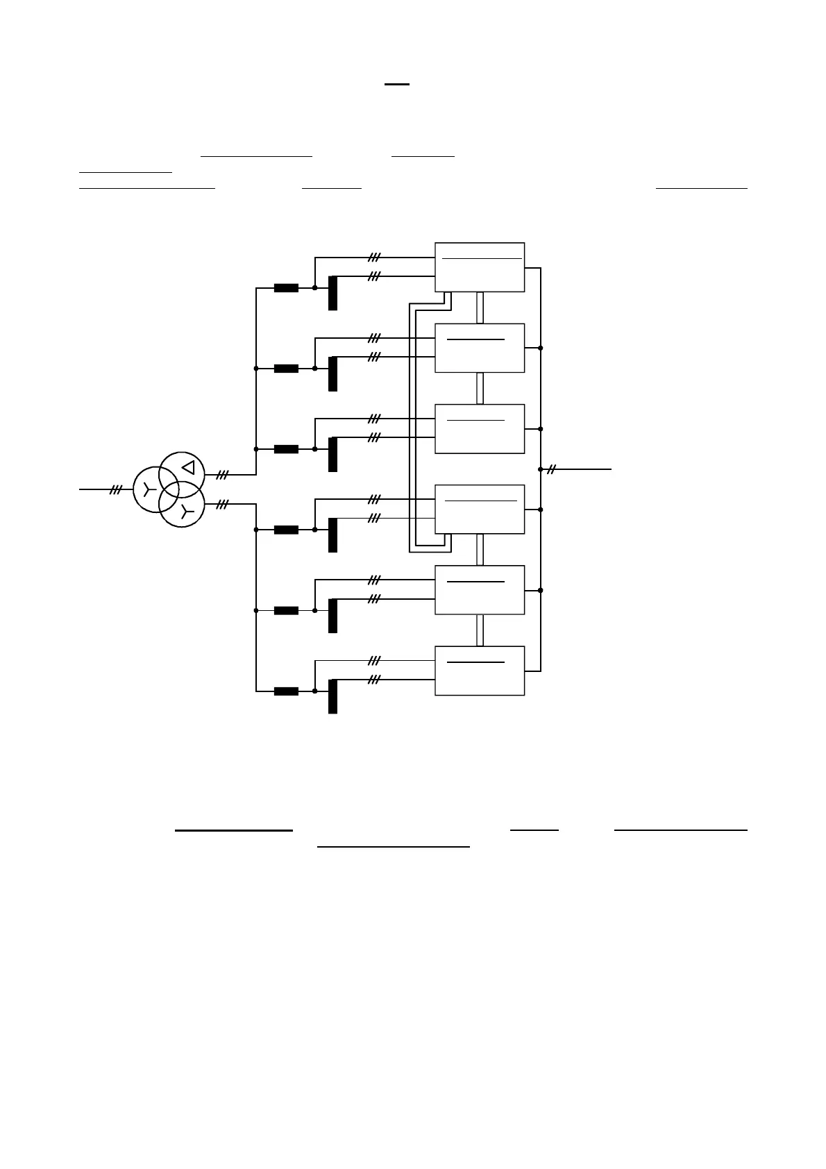
c) Example of a configuration for 12-pulse mode and parallel connection of units of size K to obtain the
maximum output current
In the following example of a power section arrangement with autotransformers and a reactor arrangement
for a "high-power supply", 2 groups of size K units operate in 12-pulse mode to obtain the maximum possible
output current. The first group of units
comprises a basic unit parameterized as a "12-pulse master" to which
2 parallel units
(not containing a CUR electronic module, see Section 3.7) are connected in parallel. The
second group of units
comprises a basic unit parameterized as a "12-pulse slave" to which 2 parallel units
are also connected in parallel.
X27
X28
X27
X28
X27
X28
X27
X28
X117
X117
Arrangement for high-power system
Mains
DC link
"12-pulse transformer"
Reactor
Reactor
Reactor
Reactor
Reactor
Reactor
Autotransformer
Auto-
transformer
Autotransformer
Autotransformer
Auto-
transformer
Auto-
transformer
12-pulse master
Rectification
Regeneration
12-pulse slave
Rectification
Regeneration
Parallel unit
Rectification
Regeneration
Parallel unit
Rectification
Regeneration
Parallel unit
Rectification
Regeneration
Parallel unit
Rectification
Regeneration
Figure 3.41 Example of a configuration for 12-pulse mode and parallel connection of units of size K to obtain the maximum output
current
3.8.3 Parameterization for 12-pulse mode
In this application, two 6SE70 units
(rectifier/regenerating units) are coupled via the SST2 serial interface
(optional RS485 interface PTP1) using "Peer-to-Peer" protocol
. One unit is parameterized as a 12-pulse
master and one is parameterized as a 12-pulse slave.
Selection of the basic or reserve setting (index i001 or i002) of the appropriate "Source selection parameter“
(P554, P555, ...) is described in Section 4.1.2.
AoteWell Automation Sales Team
Buy Siemens PLC HMI Drives at AoteWell.com
 Loading...


