09.02 Connection
Siemens AG 6SE7087-6AK85-1AA0
3-47
Rectifier/Regenerating Unit Operating instructions
3.7 Parallel connection of parallel unit(s), size K
The output current can be increased by connecting up to 2 "parallel" units of identical rated current in parallel
with the power section of a rectifier/regenerating unit of size K (basic unit).
If less power is required in the regenerative feedback direction than in the infeed direction, on Software Version
3.2 and higher of an IR unit it is possible to connect one or two infeed unit parallel unit(s) with the same rated
current in parallel. (For permitted power section combinations, see Chapter 5, P076. See also Chapter 7, F061,
interference value 7 and 8).
The following table shows for each basic unit order number, the order number for the corresponding parallel unit
that can be connected in parallel.
Order No. for basic unit Order No. IR parallel unit
for parallel connection
(infeed and regenerative feedback
direction)
Order No. IR parallel unit
for parallel connection
(infeed direction only)
6SE7041-3EK85-1AA0 6SE7041-3EK85-1AD0 6SE7041-3EK85-0AD0
6SE7041-8EK85-1AA0 6SE7041-8EK85-1AD0 6SE7041-8EK85-0AD0
6SE7041-3FK85-1AA0 6SE7041-3FK85-1AD0 6SE7041-3FK85-0AD0
6SE7041-5FK85-1AA0 6SE7041-5FK85-1AD0 6SE7041-5FK85-0AD0
6SE7041-8FK85-1AA0 6SE7041-8FK85-1AD0 6SE7041-8FK85-0AD0
6SE7041-3HK85-1AA0 6SE7041-3HK85-1AD0 6SE7041-3HK85-0AD0
6SE7041-5HK85-1AA0 6SE7041-5HK85-1AD0 6SE7041-5HK85-0AD0
6SE7041-8HK85-1AA0 6SE7041-8HK85-1AD0 6SE7041-8HK85-0AD0
Table 3.11 Corresponding basic and parallel units
The parallel units have the same technical data as the corresponding basic units.
The parallel units do not include a CUR electronic module and are fitted with a C98043-A1695 (A23) Power
Interface module instead of a C98043-A1685 (A23) Power Interface module.
The parallel units do not
require a separate external 24V power supply (via X9). The contactor for the parallel
unit(s) is controlled via X9 of the basic device. Please observe contact ratings (if not sufficient, use an auxiliary
relay).
A 50-core ribbon cable is used to transfer firing pulse signals and monitoring signals. It also carries the power
supply for the parallel units.
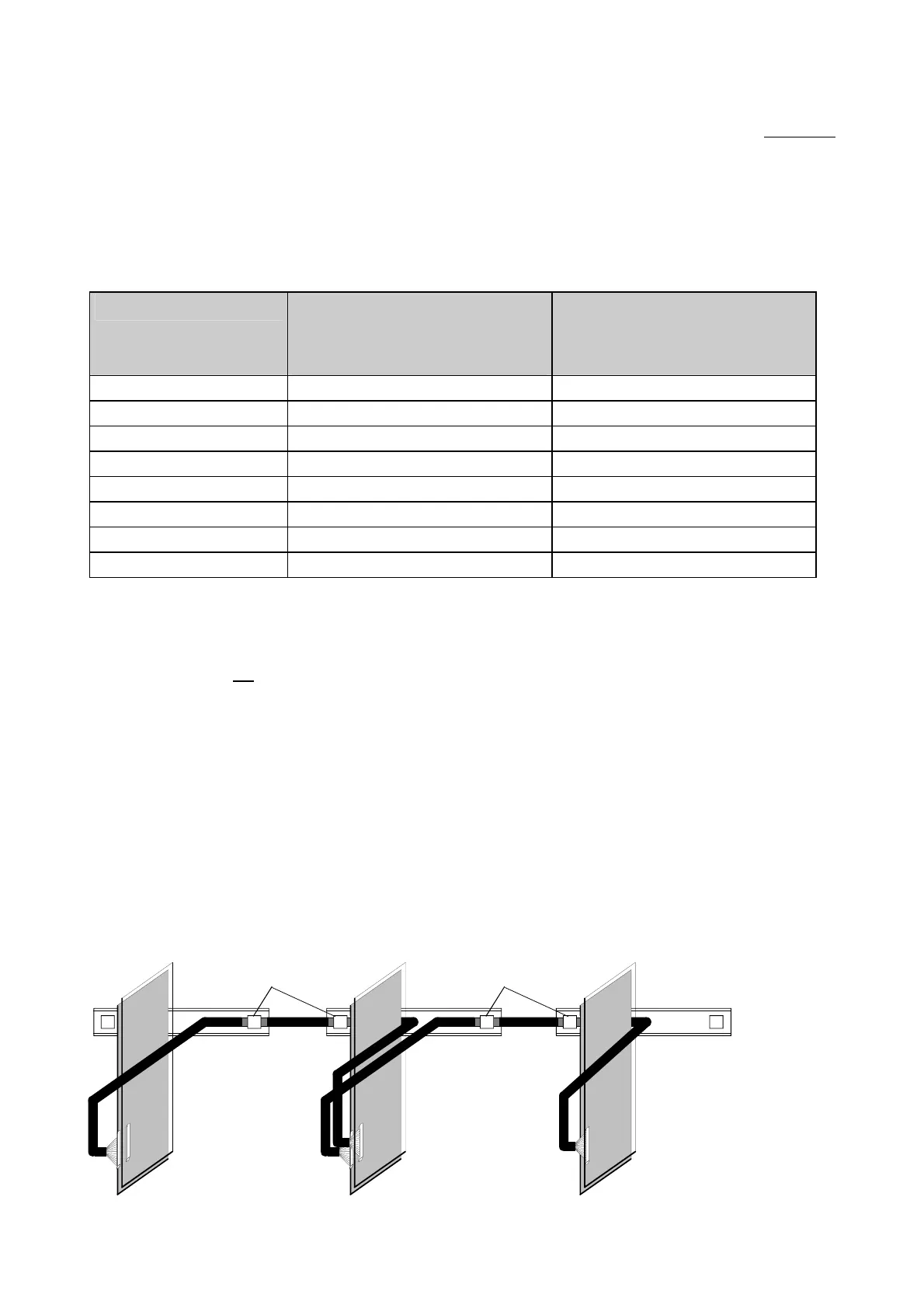
Parallel connection to a basic unit:
The female terminal strip X27 on module A23 of the basic unit is connected to the male terminal strip X28 on
module A23 of the parallel unit via a 50-core ribbon cable.
Parallel connection of a second parallel unit:
The female terminal strip X27 on module A23 of the first parallel unit is connected to the male terminal strip X28
on module A23 of the second parallel unit via a 50-core ribbon cable.
The parallel unit(s) should be installed to the left of the basic unit (see Figure 3.36).
X27
X27
X28
X27
X28
A23
C98043-
A1695
A23
C98043-
A1695
A23
C98043-
A1685
Secure cable, whose insulation has
been stripped over a length of 30mm,
by means of a shield clamp.
Parallel unit Parallel unit Basic unit
Secure cable, whose insulation has
been stripped over a length of 30mm,
by means of a shield clamp.
Figure 3.36 Connection of firing pulse signals and monitoring signals for the parallel units
AoteWell Automation Sales Team
Buy Siemens PLC HMI Drives at AoteWell.com
 Loading...


