Start-Up 09.02
4-4 Siemens AG 6SE7087-6AK85-1AA0
Rectifier/Regenerating Unit Operating Instructions
4.2 Initial start-up
4.2.1 Preparatory measures
- Transporting, unpacking, assembling: refer to Section 2
- Connecting-up: Refer to Section 3
NOTE
The rectifier/regenerating feedback unit is a line-commutated converter. The main contactor, which connects
the IR unit to the network, must always be actuated
by the device itself via the isolated contacts X9.4 and
X9.5. (See also the block diagrams with connection suggestions as described in Chapter 3.5). Direct,
externally controlled opening of the main contactor (e.g. with system fault signals or emergency shutdown)
during operation of the IR unit can cause uncontrollable excessive current (due to "commutation failure"). This
can cause damage to the unit or in the system. The IR unit must always be switched on/off via the signal
sources selected according to parameters P554 to P557. The relay for main contactor actuation (isolated
contacts X9.4 and X9.5) is actuated depending on these signal sources. The internal device control in
regenerative feedback operation in particular ensures a correct switch-off sequence.
- Read "Introduction and handling the start-up instructions": Section 4.1
- Forming: If the inverter(s) connected have been switched off continuously or not connected for more than a
year, is/their link capacitors must be formed (see Section 4.3.9.6).
- Connect-up the supply and electronics power supply of the converter with the front panel closed.
The rectifier/regenerating unit is supplied with the "factory setting" (refer to Section 5 "Parameter list",
column 4) and access stage 2 (standard mode). That means:
- The settings of the rectifier/regenerating unit data correspond to the unit type according to the MLFB
(i.e. converter already initialized).
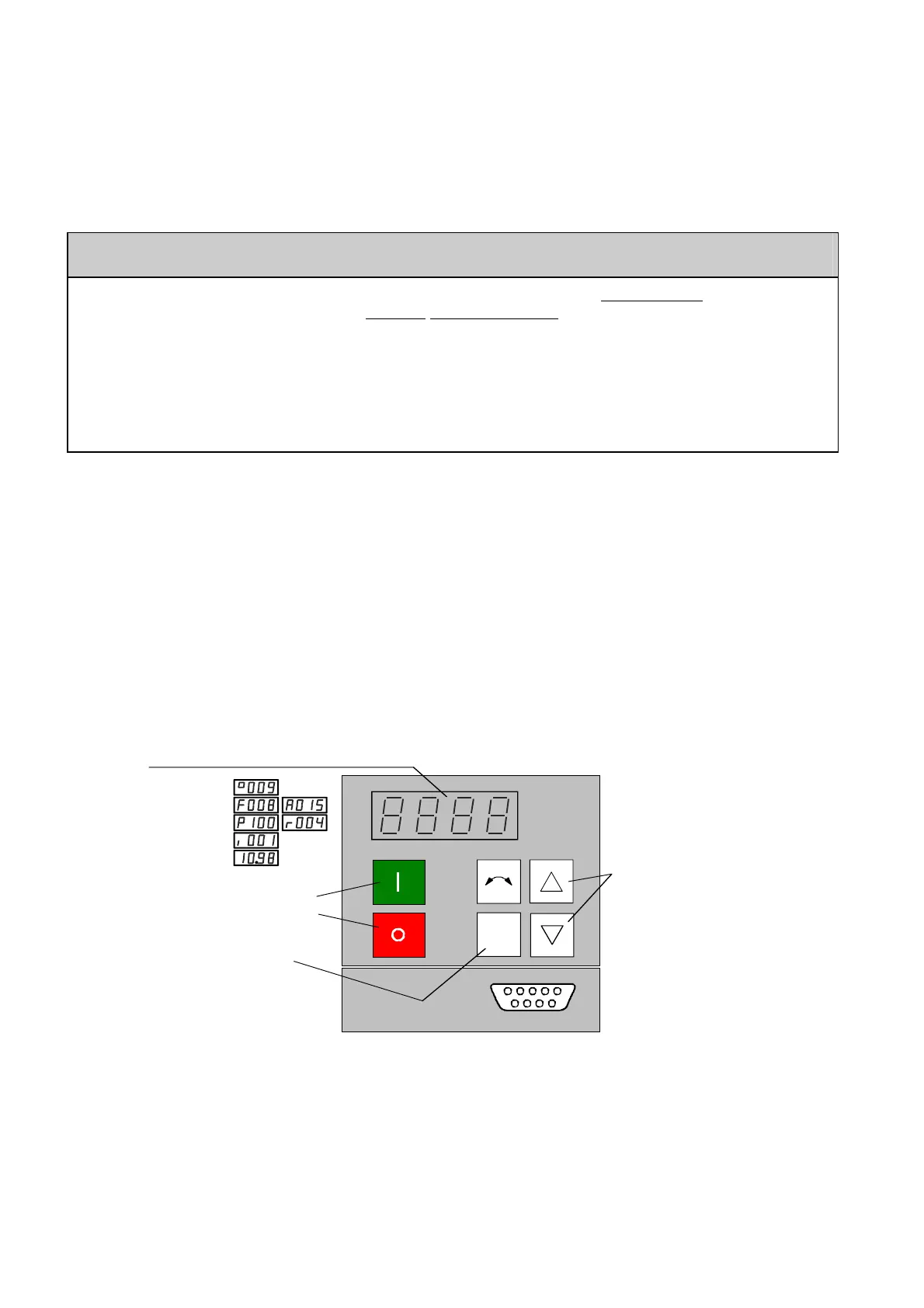
When supplied, the converter is controlled and parameterized by the parameterizing unit (PMU) located on the
front side of the converter.
P
Switch-on
Switch-off
Displays:
Statuses
faults, alarms,
parameter numbers,
index numbers,
parameter values
Fault acknowledgement and
changeover between:
Parameter number
Parameter index
Parameter value
Parameters
Indices
Parameter values
Raise/lower
to select:
A detailed description of the displays as well as the parameterizing and operator control possibilities of the
rectifier/regenerating unit via the PMU, is provided in Section 6 "operator control".
Parameterization is realized according to Sections 4.2.2 and 4.2.3
AoteWell Automation Sales Team
Buy Siemens PLC HMI Drives at AoteWell.com
 Loading...


