Connection 09.02
3-48 Siemens AG 6SE7087-6AK85-1AA0
Rectifier/Regenerating Unit Operating instructions
NOTE
The permissible output current for a parallel arrangement is reduced (due to the current division between the
power sections) by 10% as compared with the sum of the rated currents of the separate power sections.
The following is required to ensure even current distribution between the basic unit and parallel unit(s).
♦ Identical phases for the power section connections of the rectifier/regenerating units between the basic
units and parallel unit(s)
♦ Use of identical power components (see above table for the corresponding parallel units and basic units)
♦ Commutating reactors and autotransformers specific for each basic and parallel unit with identical technical
data. Each separate
parallel path must have a minimum u
k
value of 2%.
In the case of extremely high u
k
values for the mains supply (low-power system), the primary side of the
autotransformer should be connected directly to the supply (before the commutating reactors), so that the
total u
k
value will not be too high in the regenerative direction.
With an extremely high total u
k
value in the regenerative direction, it may be necessary due to the
increased thyristor current commutating time, to reduce the inverter step limit (parameter P776). This may
mean it is necessary to reduce Ud.
X27
X28
X27
X28
X27
X28
X27
X28
Mains
DC link
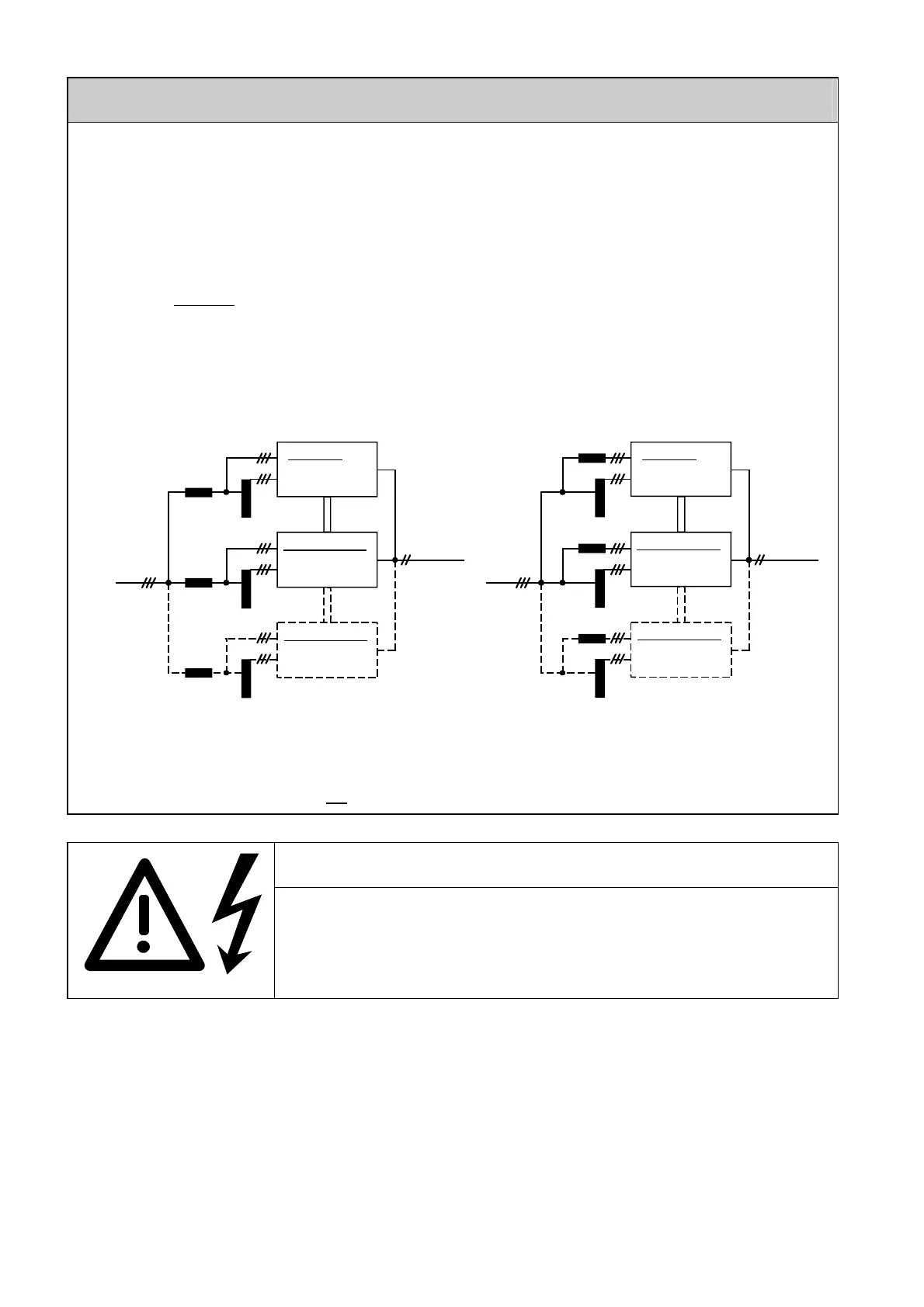
Arrangement for high-power system
Mains
DC link
Parallel unit (1)
Rectification
Regeneration
Basic unit
Rectification
Regeneration
Parallel unit (2)
Rectification
Regeneration
Parallel unit (1)
Rectification
Regeneration
Basic unit
Rectification
Regeneration
Parallel unit (2)
Rectification
Regeneration
Arrangement for low-power system
♦ Identical fuses for basic unit and parallel unit(s)
♦ Identical cable lengths leading to the power section connections of the basic and parallel units
Output reactors in the DC circuit are not
permitted.
WARNING
Fault-free operation can only be guaranteed if the phases at the power section
terminals (U1/L1, V1/L2, W1/L3, 1U2/1T1, 1V2/1T2, 1W2/1T3, C/L+ and D/L-)
between the basic unit and parallel unit(s) are identical.
Non-compliance with this condition may result in destruction of the power
sections of the basic and parallel units.
The maximum permissible total cable length between the basic unit and parallel unit 1 or parallel unit 2 (if
present) is 15 m.
A 50-way shielded round cable with a length of 4 m is contained in the scope of supply of a parallel unit (spare
parts order No.: 6SY7010-8AA00).
Order No. for one cable "10 m round, screened": 6QX5368 (other lengths on request):
On connecting this round, 50-core cable with a diameter of 14 mm, its screen has to be laid bare by cutting
away the insulation and it must be connected to earth on both devices. To ensure the interference immunity of
the system, it is recommended that the cable is laid in an earthed metal pipe of at least 50 mm in diameter (to
allow the plug to be fed through).
AoteWell Automation Sales Team
Buy Siemens PLC HMI Drives at AoteWell.com
 Loading...


