Maintenance 09.02
8-6 Siemens AG 6SE7087-6AK85-1AA0
Rectifier/Regenerating Unit Operating Instructions
Replacing the PMU for size C
♦ Release the snaps on the front cover
♦ Open-up the front cover
♦ Withdraw connector X108 on the CUR
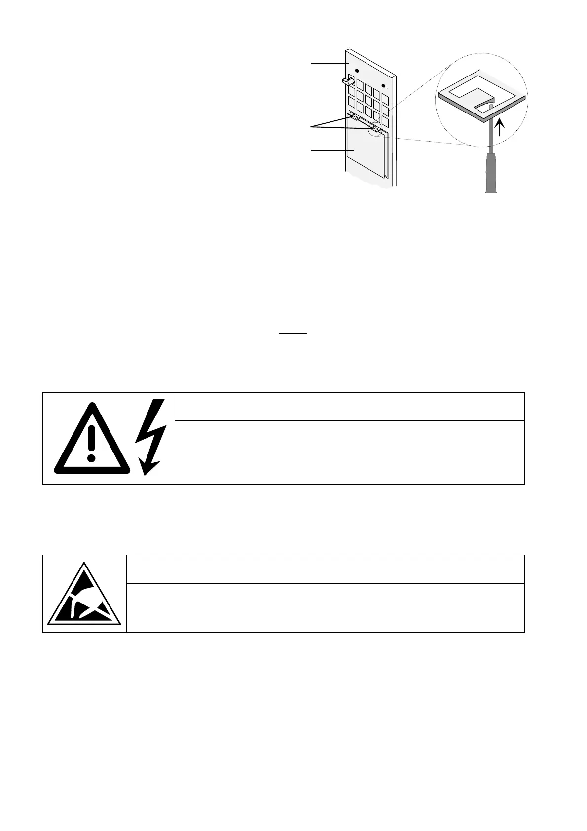
♦ Carefully depress the latch upwards on
the inner side of the front cover using a
screwdriver
♦ Remove the PMU board
♦ Install the new PMU board in the
inverse sequence.
Rear side of
the front cover
Snap catch
PMU board
Figure 8.6 Rear side of the front cover with PMU board
Replacing the EPROM on the CUR module (upgrading to a new software version)
On setup and during servicing work, the current parameter settings in the logbook in Chapter 12 should be
saved For information on reading out the parameters changed from the factory settings easily, see Section
4.3.9.3 (saving the parameter values using DriveMonitor) and Section 4.3.9.8 (displaying modified parameters).
It should be checked that these entries are up-to-date before
the EPROM is replaced because when the
electronics supply voltage is switched on again, the function "generate factory settings" is carried out
automatically (see Section 4.3.9.1). Then only the values of parameters P070 and P077 are retained.
WARNING
The EPROM must only be replaced by qualified persons. The EPROM must
not be removed or inserted under a live voltage.
Non-observance of warning notices can result in death, severe personal injury
or considerable property damage.
The EPROM is located in slot D14 of module CUR.
CAUTION
The modules contain electrostatically sensitive devices. You must discharge your own
body before touching an electronic module. This is best done by touching a conductive
earthed object (e.g. a bare metal part of the control cabinet) directly beforehand.
AoteWell Automation Sales Team
Buy Siemens PLC HMI Drives at AoteWell.com
 Loading...


