EasyManuals Logo

Siemens SINAMICS G120C User Manual

Siemens SINAMICS G120C
478 pages
To Next Page IconTo Next Page
To Previous Page IconTo Previous Page
Page #105 background imageLoading...
Page #105 background image
4.10.7 Connecting a failsafe digital input
Overview
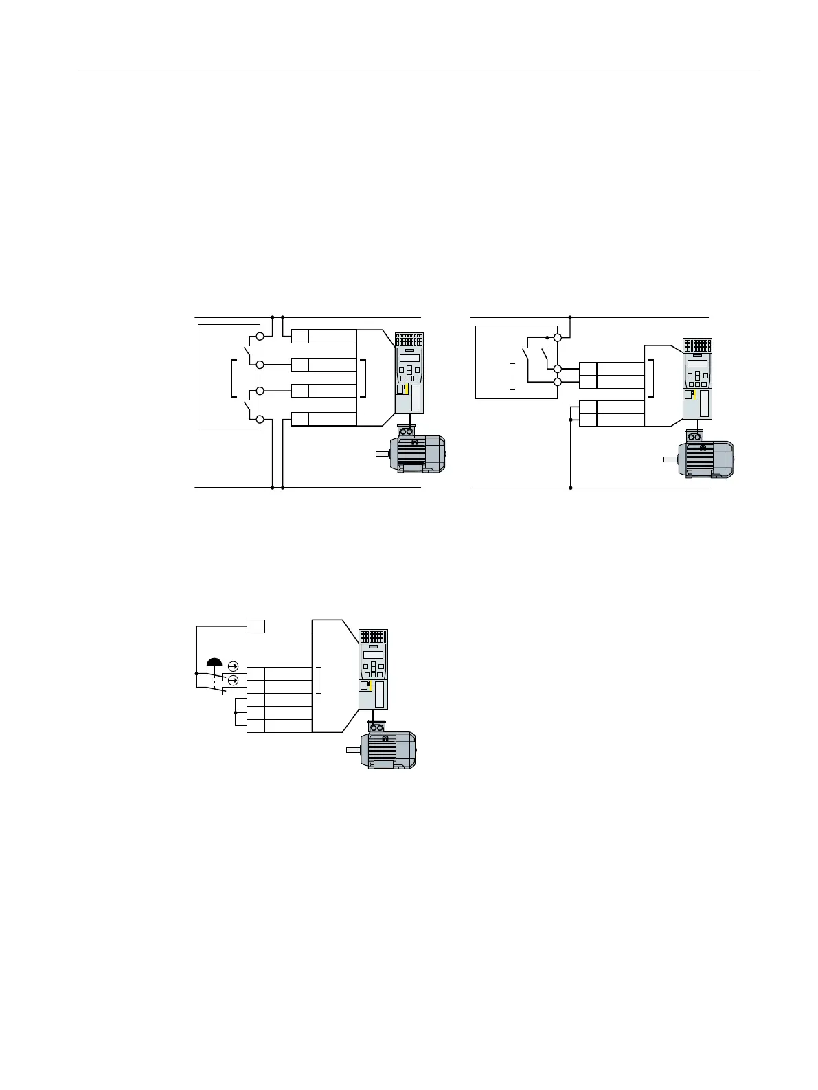
The converter has the following connection options for failsafe digital inputs:
Sensor output
PM-switching failsafe digital output
PP-switching failsafe digital output
9'&
0
0
3
33
',
',&20
',
',&20
9'&
0
',
',
',&20
',&20
)',)'2
)'2
)',
Figure4-38 Connecting a PM-switching and PP-switching failsafe digital output
Function description
The following examples comply with PL d according to EN 13849-1 and SIL2 according to IEC
61508 for the case that all components are installed within one control cabinet.
)',
9RXW
',
',
',&20
',&20
*1'
Figure4-39 Connecting a sensor, e.g. Emergency Stop mushroom pushbutton or limit switch
Installing
4.10Connecting the interfaces for the converter control
SINAMICS G120C Converters
Operating Instructions, 02/2023, FW V4.7 SP14, A5E34263257B AK 103

Table of Contents

Other manuals for Siemens SINAMICS G120C

Questions and Answers:

Question and Answer IconNeed help?

Do you have a question about the Siemens SINAMICS G120C and is the answer not in the manual?

Siemens SINAMICS G120C Specifications

General IconGeneral
Communication InterfacesPROFINET, PROFIBUS, USS, Modbus RTU
Protection ClassIP20
Ambient Temperature-10°C to +50°C
Storage Temperature-40°C to +70°C
Power Range0.55 kW to 132 kW
Voltage Range380 V to 480 V
Output Voltage0 V to Supply Voltage
Frequency Range0 Hz to rated output frequency
Control ModesVector control with encoder
ProtectionOverload, overvoltage, undervoltage, short circuit, ground fault
Relative Humidity5% to 95%, non-condensing
AltitudeUp to 2000 m without derating

Related product manuals