Installing the Control System
2.2 Interfaces and cables
2-20
SINUMERIK 802C
6FC5 597–3AA20–0BP2 (01.02)
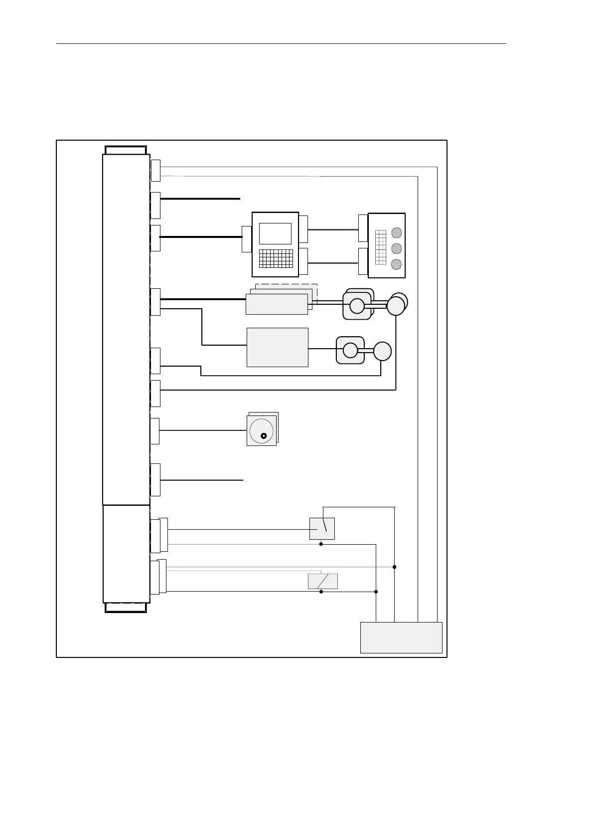
Connecting cables
The components are wired up as shown in the Connection Diagram 2-4. For the cables requi-
red, please refer to the diagram below.
ECU
Op. Panel
DI/O16
ANALOG DRIVE
ANALOG MOTOR
SPINDLE
DRIVE
SPINDLE MOTOR
ENCODER
Hand Wheels
Sensor
Actor
Power Supply
P24M
1...16
1...16
RS232
Machine
Control
Panel
Wire (1.0...2.5)
Wire (0.14...1.5)
Wire (0.14...1.5)
flat or round
cable
P24M
DC24V
RS232
OPI
AXIS
SPINDLE
ENCODER
ENCODER
MPG
DI
IN 0..7
IN 8..15
OUT0..7
OUT8..15
IN
M
L+
OUT
M
L+
M
X1X2X8
X7X6X10
X20X2003
X2004
X2005
X2006
X1009
X1001X1002
X1201X1202
1)
1)
NC READY
X3–X5
Fig. 2-4 SINUMERIK 802C connection diagram
1) Ribbon cable (included in scope of supply)