Installing the Control System
2.6 LEDs and operating elements on the ENC
2-38
SINUMERIK 802C
6FC5 597–3AA20–0BP2 (01.02)
2.6 LEDs and operating elements on the ENC
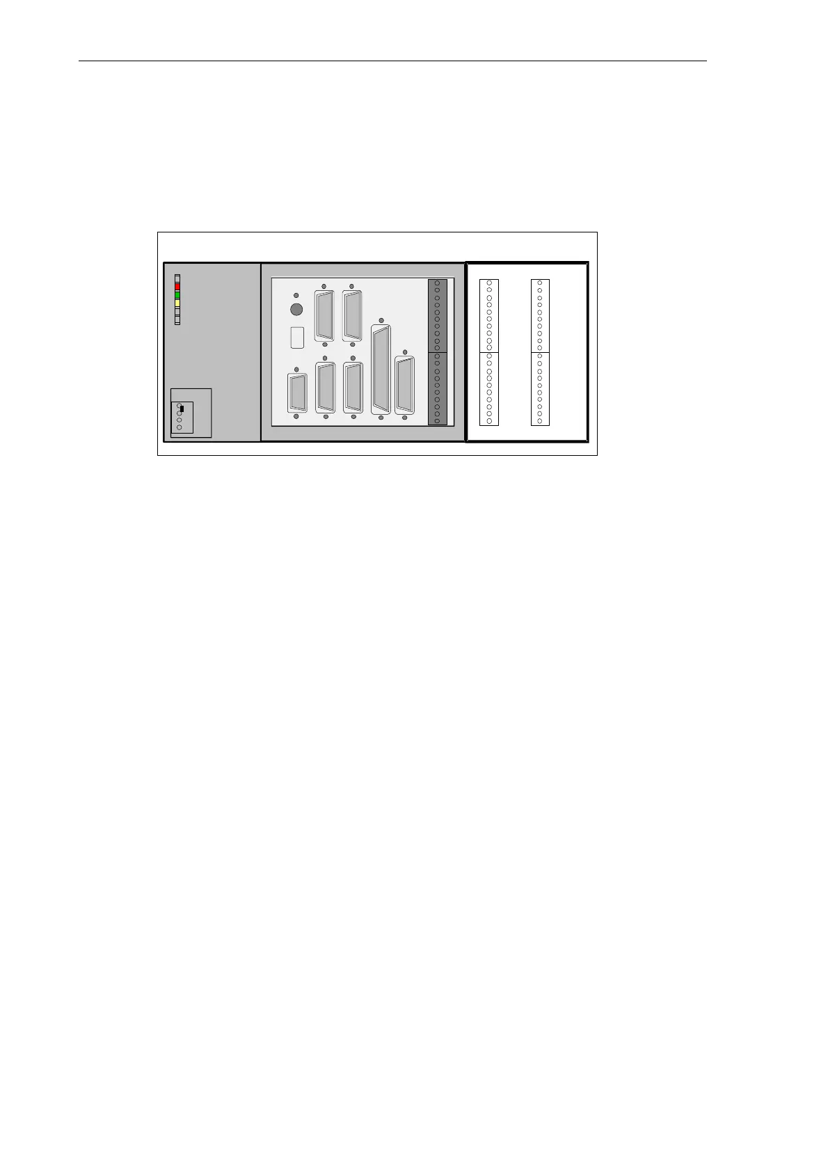
Error and status LEDs
There are three LEDs on the front panel of the ENC.
X2003 X2005
X2004 X2006
0
1
2
3
4
5
6
7
M
L+
0
1
2
3
4
5
6
7
M
8
9
10
11
12
13
14
15
M
L+
8
9
10
11
12
13
14
15
M
IN
OUT
ENC DI/O16
DC24V X1
RS232
X2
SPINDLE
X5
ENCODER3
X6
OPI
X8
AXIS
X7
X10
MPG
DI
X20
ERR
DIAG
POK
PE
L+
M
M
ENCODER2
X4
ENCODER1
X3
S2
S3
D15
Fig. 2-9 User interfaces
ERR (red)
Group error
This LED indicates an error condition of the ENC.
POK (green)
Power OK
The power supply is ready.
DIAG (yellow)
Diagnostics
This LED indicates various diagnosis states. Under normal operating conditions, this LED
flashes 1:1.
Start–up switch (S3)
This rotary switch is intended to assist start–up.
Position 0: Normal operation
Positions 1-4: Start–up
cf. also Section 4.2, Table 4-2