Installing the Control System
2.3 Connecting the individual components
2-23
SINUMERIK 802C
6FC5 597–3AA20–0BP2 (01.02)
Signal names
OPD[0...3] LCD Data 0...3
OPCP1 LCD Latch
OPS LCD Frame
OPCP2 LCD Clock
OPRXD OP Receive Data
OPTXD OP Transmit Data
OPCTS OP Clear to Send
ENRXD ECU Receive Data
ENTXD ECU Transmit Data
ENRTS ECU Request to Send
P24_OP DC24V
M_OP Ground
Signal level
RS422 / LVDS
Signal type
VO Voltage output
VI Voltage input
O Output
I Input
2.3.2 Connecting the feed drives and the spindle (X7)
Connector pin assignment on the ENC side
Feed drive interface
Connector designation: X7
AXIS 1-4
Connector type: 50–pin sub–D plug connector
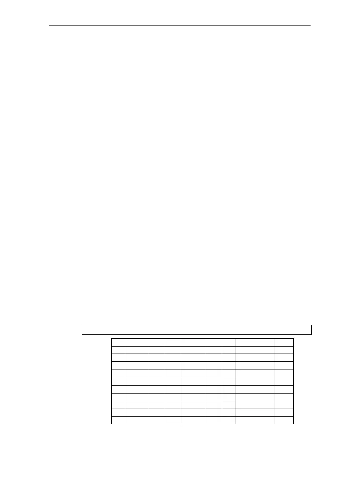
Table 2-3 Pin assignment of connector X7
X7
Pin Signal Type Pin Signal Type Pin Signal Type
1 SW1 VO 18 34 BS1 VO
2 BS2 VO 19 35 SW2 VO
3 SW3 VO 20 36 BS3 VO
4 BS4 VO 21 37 SW4 VO
5 22 38
6 23 39
7 24 40
8 25 41
9 26 42
10 27 43