Start-Up
4.3 Starting up the PLC
4-59
SINUMERIK 802C
6FC5 597–3AA20–0BP2 (01.02)
The control system is able store max. 4,000 instructions and 1,000 symbols. The required PLC
memory is influenced by the following components:
S Number of instructions
S Number and length of the symbol names
S Number and length of the comments
S7–200 ladder diagram
A ladder diagram is a graphical programming language similar to electric circuit diagrams.
When creating a program using the ladder diagram form, then you will work with graphical
components to create the networks of your logics. To create your program, you can use the
following elements:
S Contacts constitute a switch through which the current can flow. Current, however, will only
flow through a normally open contact if the contact is closed (logical
value 1). Current will flow through a normally closed contact or a negated contact (NOT) if
the contact is open (logical value 0).
S Coils constitute a relay or an output which is updated by the signal flow.
S Boxes constitute a function (e.g. a timer, counter or arithmetic operation) which is carried
out at the moment when the signal flow reaches the box.
A network consists of the elements mentioned above, forming a closed circuit. The current
flows from the left conductor bar (in the ladder diagram symbolized by a vertical line at the left
window) through the closed contacts, enabling coils or boxes.
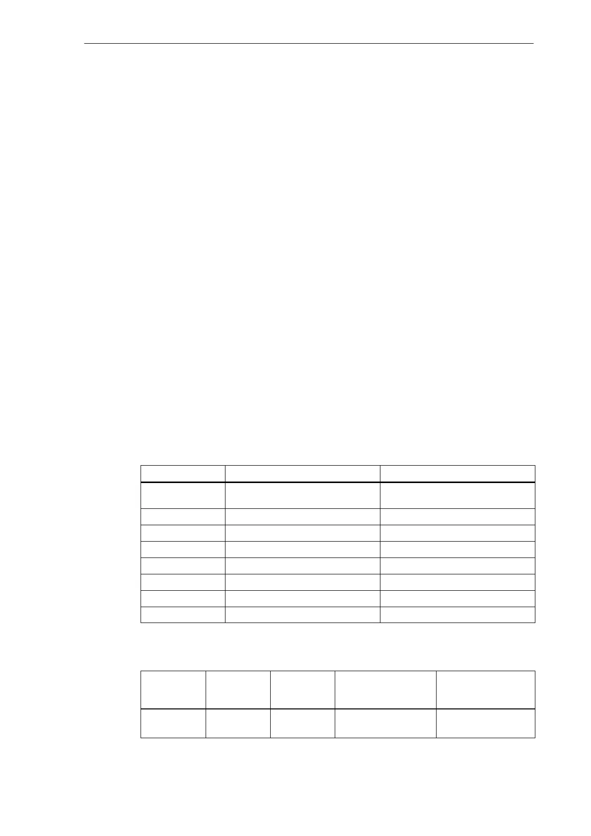
Overview of commands
Table 4-7 Operand identifers
Operand ID
Description Range
V Data V0.0 to V79999999.7 (see Table
4–8)
T Timers T0 to T15
C Counters C0 to C31
I Map of digital inputs I0.0 to I7.7
Q Map of digital outputs Q0.0 to Q7.7
M Flags M0.0 to M127.7
SM Special flags SM0.0 to SM 0.6 (see Table 4–10)
AC ACCU AC0 ... AC3
Table 4-8 Generating the addresses for the V range (see user interface)
Type Code
(DB No.)
Range No.
(Channel/
Axis No.)
Subrange Offset Addressing
00
(00–79)
00
(00–99)
0
(0–9)
000
(000–999)
symbolic
(8–digit)