Detailed Description
2.7 Structure and functions of the basic program
PLC Basic Program Solution Line (P3 sl)
Function Manual, 08/2005 Edition, 6FC5397-0BP10-0BA0
2-35
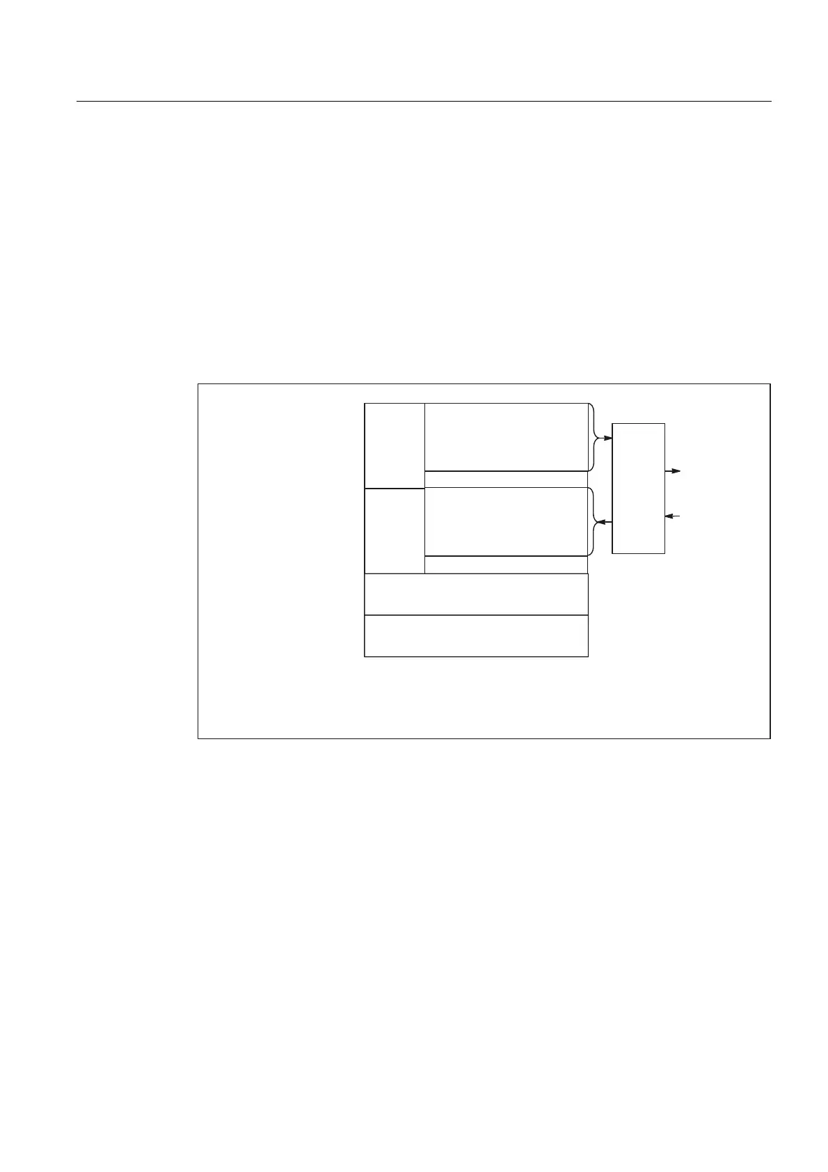
MCP interface in the PLC
The signals from the machine control panel are routed by default via the I/O interface to the
PLC area. A distinction must be made between NC and machine-specific signals. NC-
specific key signals are distributed to the relevant mode-group-, NCK-, axis- and spindle-
specific interface by FC19 (or FC24, FC25, FC26, depending on the type of MCP) by default.
The reverse applies to the associated status signals, which are routed to the MCP interface.
For this purpose, FC 19 or the other blocks mentioned above must be called in the user
program.
Customized keys, which can be used to trigger a wide range of machine functions, must be
evaluated directly by the user program. The user program also routes the status signals to
the output area for the LEDs.
)&
'!Q P R S
5HFHLYHGDWD
PRQLWRULQJ
0RQLWRULQJRIWUDQVPLW
GDWD
'HIDXOWVHWWLQJ
6WDWXVRIFXVWRPL]HGNH\V
$FWLYHGLUHFWLRQNH\
)HHGUDWHVSLQGOH1&VWDWXV
&XUUHQW,1&PRGH
&XUUHQWPRGH
8VHUNH\V
.H\ORFNVZLWFK
'LUHFWLRQNH\V
)HHGUDWHVSLQGOHRYHUULGH
,1&PRGH
2SHUDWLQJPRGHV
/LJKW
HPLWWLQJ
GLRGHV
/('V
.H\
VLJQDOV
$'S
$'R
0RGH
JURXS
1&.D[LV
VSLQGOH
LQWHUIDFH
4%P
,%Q
Fig. 2-11 Interface to and from machine control panel
2.7 2.7 Structure and functions of the basic program
General
The program is modular in design, i.e., it is structured according to NCK functions.
In the operating system, a distinction is made between the following levels of execution:
• Start-up and synchronization (OB 100)
• Cyclic mode (OB 1)
 Loading...


