Detailed Description
2.4 Referencing with incremental measurement systems
Reference Point Approach (R1)
2-8 Function Manual, 08/2005 Edition, 6FC5397-0BP10-0BA0
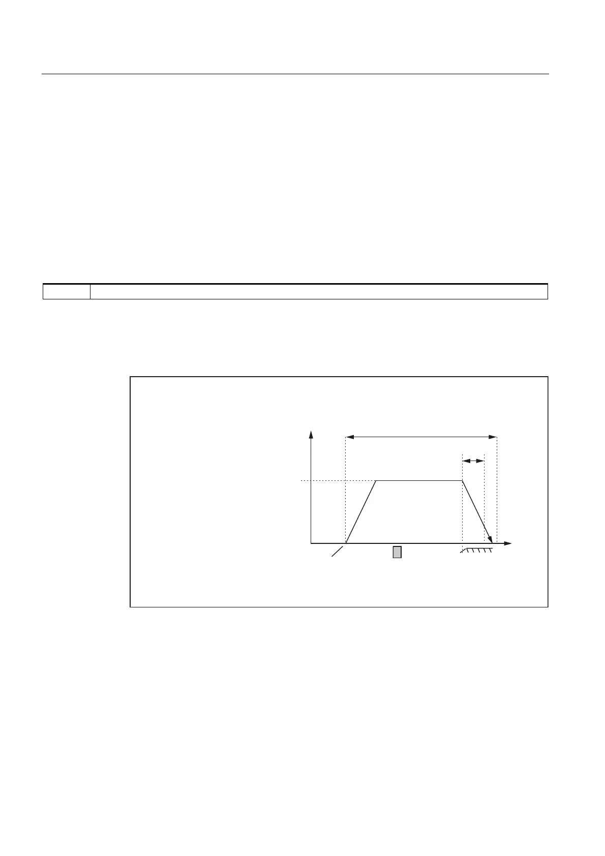
Case 1: The machine axis is positioned before the reference cam
When reference point approach is started, the machine axis accelerates in the assigned
direction:
MD34010 $MA_REFP_CAM_DIR_IS_MINUS (approach reference point in minus direction)
to the assigned reference point approach velocity before the reference cam:
MD34020 $MA_REFP_VELO_SEARCH_CAM.
The PLC user program communicates to the NC that the reference cam has been reached
via the following interface signal:
DB31, ... DBX12.7 (reference point approach deceleration)
As a result the NC decelerates to zero speed. In so doing, the following distance S
min
is
traversed, at a minimum:
S
min
= (MD34040 $MA_ REFP_VELO_SEARCH_MARKER)
2
/ 2 * (MD32300 $MA_MAX_AX_ACCEL)
This minimum distance must be covered to ensure that the machine axis exits the reference
cam in phase 2 at the assigned reference point creep velocity.
Phase 1 is now complete. Reference point approach is continued with Phase 2.
UHIHUHQFHSRLQWDSSURDFKYHORFLW\
6WDUWLQJSRVLWLRQ
RID[LV
0LQLPXPGLVWDQFH
5HIHUHQFHSRLQWFDP
9HORFLW\
PD[LPXPGLVWDQFHWRUHIHUHQFHFDP
=HURPDUN
'LVWDQFH
0'0$B5()3B0$;B&$0B',67
0'0$B5()3B9(/2B6($5&+B&$0
Fig. 2-3 Minimum distance for deceleration
 Loading...


