Detailed Description
2.7 Basic tool orientation
Tool Compensation (W1)
2-114 Function Manual, 08/2005 Edition, 6FC5397-0BP10-0BA0
System variable $TC_DPV[t, d]
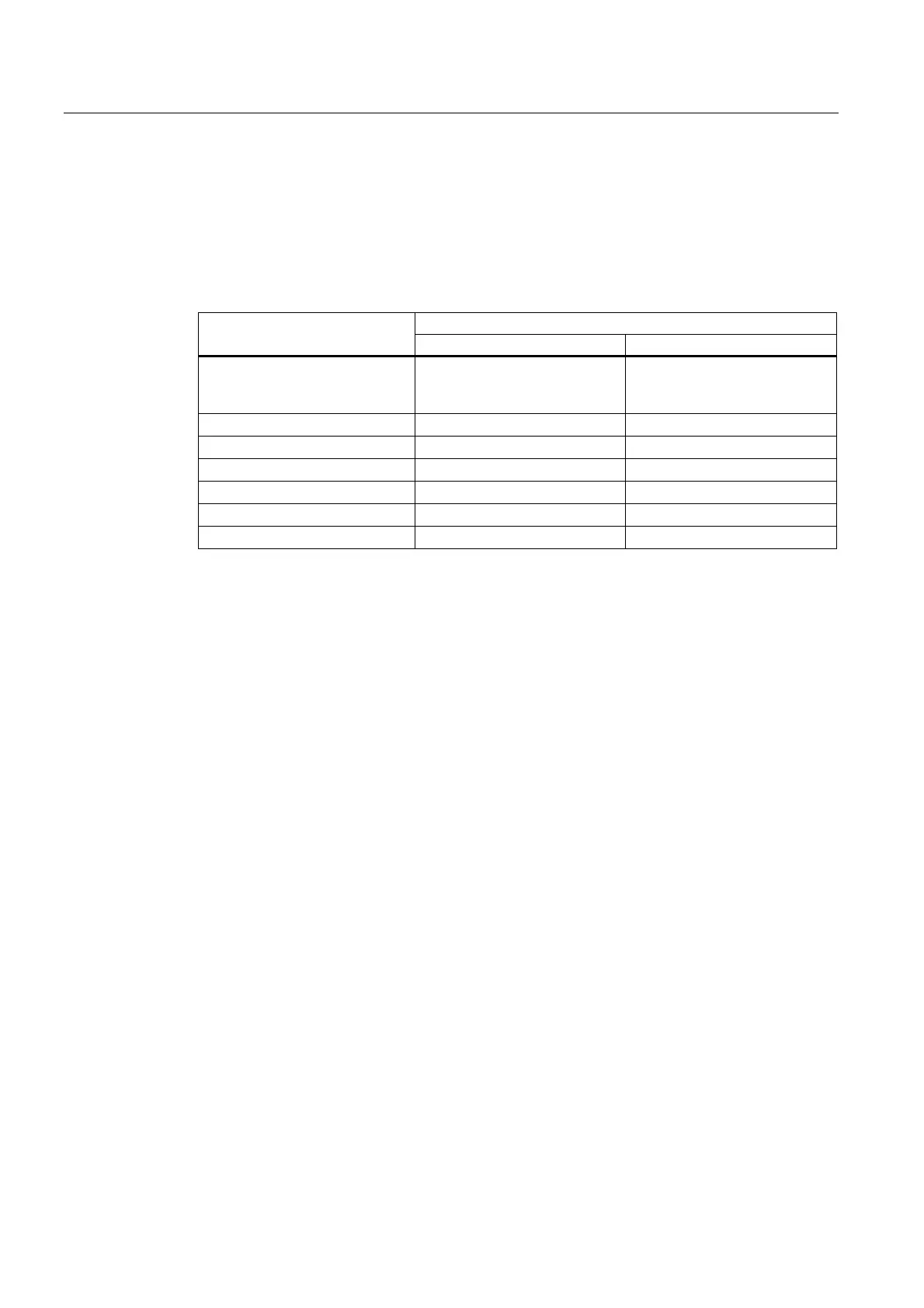
The purpose of system variable $TC_DPV[t, d] is to allow the simple specification of certain
basic orientations (parallel to coordinate axes) that are required frequently. The permissible
values are shown in the table below. The values in the first and second/third columns are
equivalent.
Basic orientation $TC_DPV[t, d]
Milling tools * Turning tools *
≤ 0 or > 6 ($TC_DPV5[t, d],
$TC_DPV4[t, d],
$TC_DPV3[t, d],) **
($TC_DPV3[t, d],
$TC_DPV5[t, d],
$TC_DPV4[t, d],) **
1 (0, 0, V) (0, V, 0)
2 (0, V, 0) (0, 0, V)
3 (V, 0, 0) (V, 0, 0)
4 (0, 0, -V) (0, -V, 0)
5 (0, -V, 0) (0, 0, -V)
6 (-V, 0, 0) (-V, 0, 0)
* Turning tools in this context are any tools whose tool type ($TC_DP1[t, d]) is between 400 and
599. All other tool types refer to milling tools.
** If all three values $TC_DPV3[t, d], $TC_DPV4[t, d], $TC_DPV5[t, d] are equal to zero in this
case, the tool orientation is determined by the active machining plane (default).
V Stands for a positive value in the corresponding system variables.
Example:
For milling tools,
$TC_DPV[t, d] = 2
is equivalent to
$TC_DPV3[t, d] = 0, $TC_DPV4[t, d] = 0, $TC_DPV5[t, d] = V.
Supplementary conditions
If the "Scratch" function is used in the RESET state, the following must be noted with respect
to the initial setting:
• The wear components are evaluated depending on the initial settings of the G-code
groups TOWSTD, TOWMCS and TOWWCS.
• If a value other than the initial setting is needed to ensure correct calculation, scratching
may be performed only in the STOP state.
 Loading...


