Examples
4.2 Examples 3–6: SETTCOR function for tool environments
Tool Compensation (W1)
4-10 Function Manual, 08/2005 Edition, 6FC5397-0BP10-0BA0
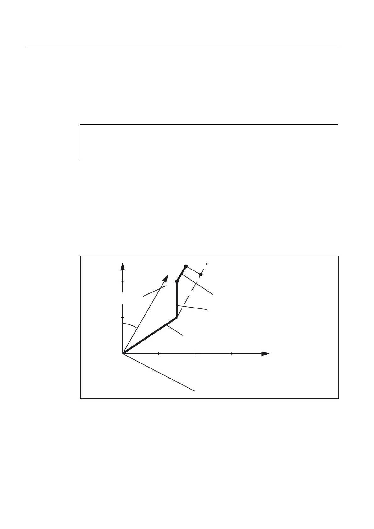
The tool is a turning tool. A frame rotation is activated in N80, causing the basic coordinate
system (BCS) to be rotated in relation to the workpiece coordinate system (WCS). In the
WCS, the compensation value (N70) acts on the geometry axis with index 1, i.e., on the
X axis because G18 is active. Since "_CORRMODE = 3", the tool wear in the direction of the
X axis of the WCS must become zero once N100 has been executed. The contents of the
relevant tool parameters at the end of the program are thus:
$TC_DP3[1,1] : 21.830 ; Geometry L1
$TC_DP4[1,1] : 21.830 ; Geometry L2
$TC_DP12[1,1] : 2.500 ; Wear L1
$TC_DP13[1,1] : -4.330 ; Wear L2
The total wear including _CORVAL is mapped onto the X' direction in the WCS. This
produces point P2. The coordinates of this point (measured in X/Y coordinates) are entered
in the geometry component of the tool. The difference vector P
2
- P
1
remains in the wear.
The wear thus no longer has a component in the direction of _CORVAL.
B&259$/ HIIHFWLYHLQ;GLUHFWLRQ
:HDU/ /
*HRPHWU\/ /
2ULJLQDO
WRROOHQJWK
;
=
;
=
3
3
3
Fig. 4-1 Tool length compensation, example 6
 Loading...


