Detailed Description
2.1 Various interface signals and functions (A2)
NC/PLC Interface Signals (Z1)
Function Manual, 08/2005 Edition, 6FC5397-0BP10-0BA0
2-29
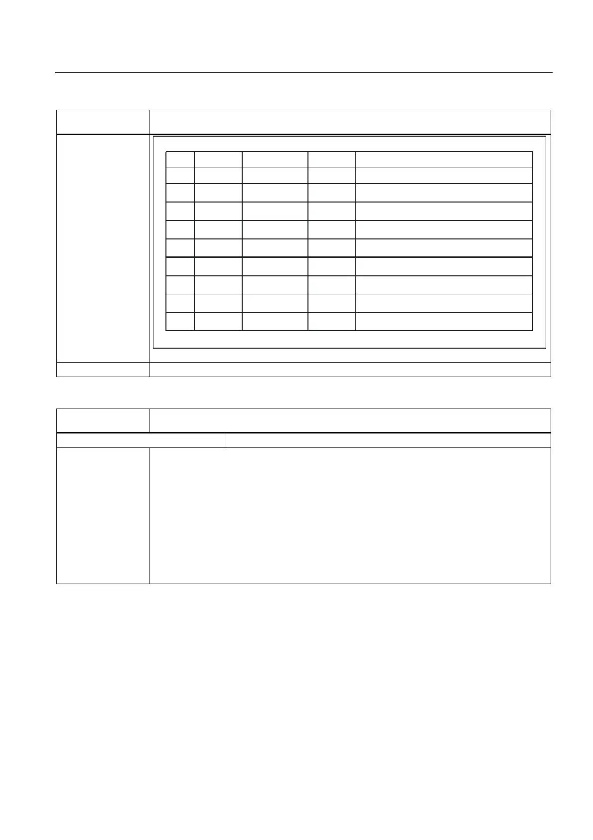
DB31, ...
DBX1.3
Axis/spindle disable
QRWVHWVHW
1R
&RXSOLQJ
3URFHGXUH
)6)$/6/$
2II
2II
2II
2II
21
21
21
21
6HWSRLQWVRID[HVDUHRXWSXW
1RVHWSRLQWRXWSXWIRU)6)$
1RVHWSRLQWRXWSXWIRU/6/$
1RVHWSRLQWRXWSXWIRU/6/$DQG)6)$
6HWSRLQWVRID[HVDUHRXWSXW
'LVDEOHQRWHIIHFWLYHIRU)6)$
'LVDEOHDOVRHIIHFWLYHIRU)6)$
1RVHWSRLQWRXWSXWIRU/6/$DQG)6)$
Corresponding to .... DB21, ... DBX33.7 (program test active)
DB31, ...
DBX1.4
Follow-up mode
Edge evaluation: no Signal(s) updated: cyclic
Signal state 1 Follow-up mode is selected for the axis/spindle by the PLC.
The means that the position setpoint continually tracks the actual value if the controller enable for
the drive is withdrawn.
As soon as the follow-up mode is effective, the interface signal:
DB31, ... DBX61.3 (follow-up mode active)
is set to a 1 signal.
The actual value continues to be acquired and updated. If the axis/spindle is moved from its current
position by an external effect the zero speed and clamping monitoring do not issue an alarm.
When the closed-loop control system is reactivated, a control-internal repositioning operation is
performed (REPOSA: linear approach with all axes) to the last programmed position if a part
program is active.
 Loading...


