Protection zones
4.2 Activating, deactivating protection zones (CPROT, NPROT)
Job planning
Programming Manual, 03/2006 Edition, 6FC5398-2BP10-1BA0
4-5
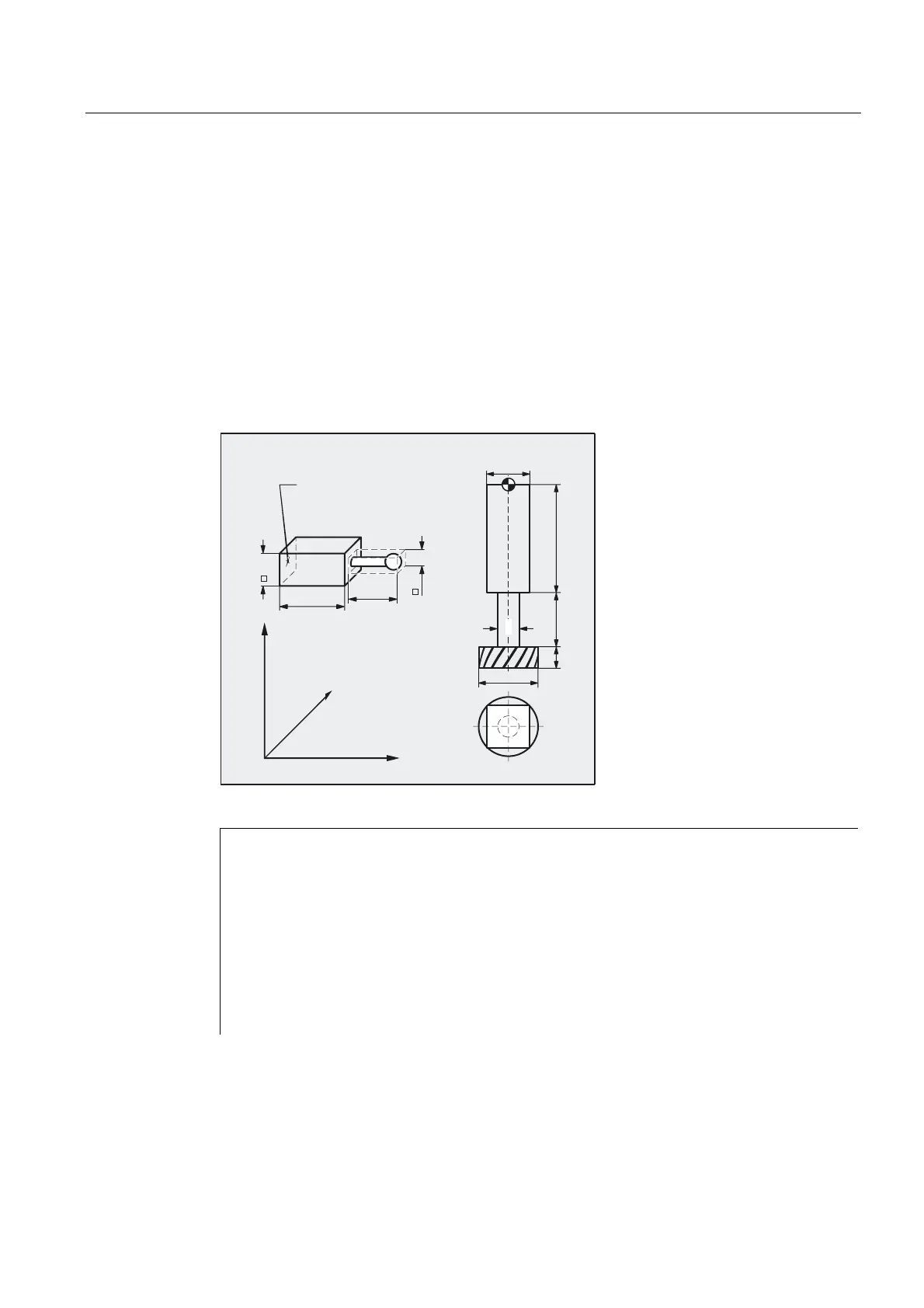
Example of milling
Possible collision of a milling cutter with the measuring probe is to be monitored on a milling
machine. The position of the measuring probe is to be defined by an offset when the function
is activated. The following protection zones are defined for this:
• A machine-specific and a workpiece-related protection zone for both the measuring probe
holder (n-SB1) and the measuring probe itself (n-SB2).
• A channel-specific and a tool-oriented protection zone for the milling cutter holder
(c-SB1), the cutter shank (c-SB2) and the milling cutter itself (c-SB3).
The orientation of all protection zones is in the Z direction.
The position of the reference point of the measuring probe on activation of the function must
be X = –120, Y = 60 and Z = 80.
5HIHUHQFHSRLQWIRU
WKHSURWHFWLRQ]RQH
RIWKHSUREH
&6%
&6%
&6%
;
=
<
Q6%
Q6%
DEF INT PROTECTB Definition of a Help variable
Definition of protection zones
G17
Set orientation
NPROTDEF(1,FALSE,3,10,–10)
G01 X0 Y–10
X40
Y10
X0
Y–10
EXECUTE(PROTECTB)
Protection zone n–SB1

 Loading...


