Tool offsets
8.8 Tool holder kinematics
Job planning
Programming Manual, 03/2006 Edition, 6FC5398-2BP10-1BA0
8-43
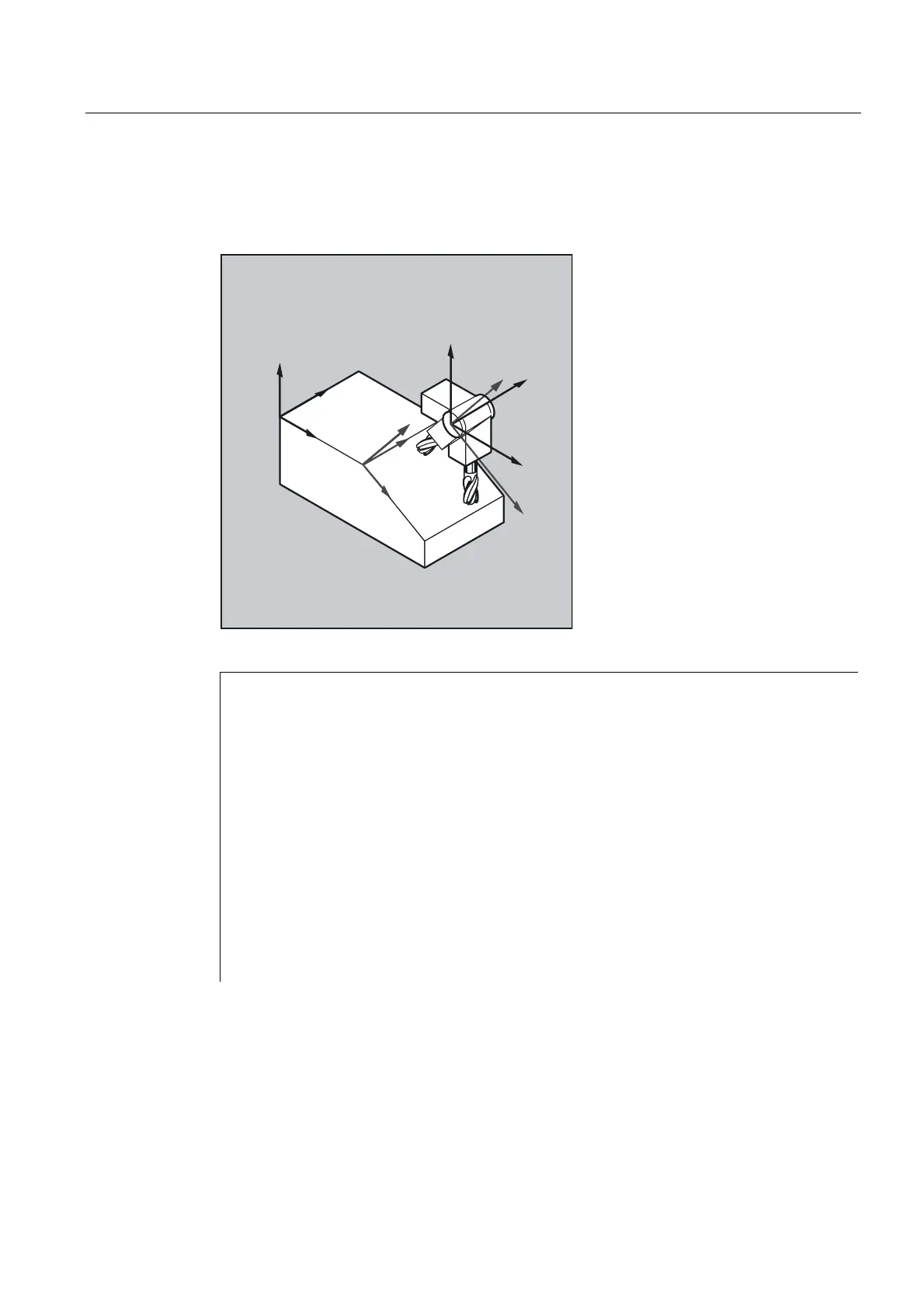
Example
The toolholder used in the following example can be fully described by a rotation around the
Y axis.
=
;
;
<
]
=
;
;
<
<
]
N10 $TC_CARR8[1]=1 ;Definition of the Y components of the
;first rotary axis of toolholder 1
N20 $TC_DP1[1,1] = 120 ;Definition of an end mill
N30 $TC_DP3[1,1]=20 ;Definition of an end mill with
;length 20 mm
N40 $TC_DP6[1,1]=5 ;Definition of an end mill with
;radius 5 mm
N50 ROT Y37 ;Frame definition with 37° rotation around
;the Y axis
N60 X0 Y0 Z0 F10000 ;Approach start position
N70 G42 CUT2DF TCOFR TCARR=1 T1 D1 X10 ;Set radius compensation, tool length
;offset in rotated frame,
;select toolholder 1, tool 1
N80 X40 ;Execute machining under a 37° rotation
N90 Y40
N100 X0
N110 Y0
N120 M30
Requirements
A toolholder can only orientate a tool in all possible directions in space if
• two rotary axes V
1
and V
2
are present.
• the rotary axes are mutually orthogonal.

 Loading...


