Connection
5
5.1 Pin assignment of the interfaces
The pins of the component interfaces are assigned as specied in the tables below. Any
deviations are indicated at the relevant point.
Signal type
I Input
O Output
B Bidirectional (inputs/outputs)
V Power supply
- Ground (reference potential) or N.C. (not connected)
5.1.1 Power supply
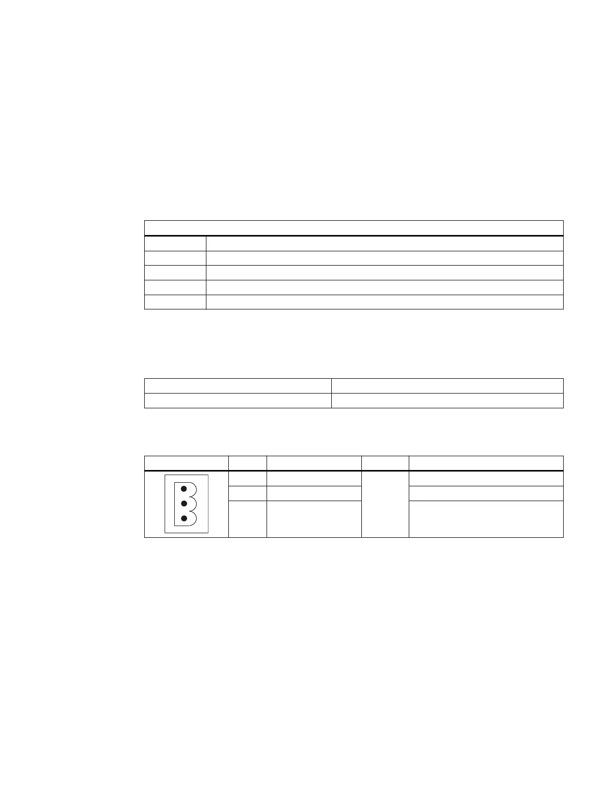
Connector type: Terminal block, 3-pin contact strip, screw type
Total cable length: 30 m
Table 5-1 Assignment of the power supply interface
Pin Name Type Meaning
1 P24 (+)
V/V/-
24 VDC potential (20.4 to 28.8 VDC)
2 M24 (-) 0V
3 Functional earth Connection for grounding the hous‐
ing
5.1.2 USB interfaces
The USB interfaces are implemented as sockets and comply with the generally valid standard.
The version information (1.1, 2.0 etc.), the maximum velocity (low speed, full speed, etc.) and
the socket type (A or B) are documented in the individual sections for the associated devices.
TCU 30.3
Equipment Manual, 03/2023, A5E40874197B AD 33

 Loading...