5.1.4 LVDS display interface
LVDS display interface channel 1
Used to connect operator panel fronts with TFT displays with 640 x 480 pixels (VGA), 800 x 600
pixels (SVGA) or 1024 x 768 pixels (XGA).
Associated interface cable: K2, max. length: 0.5 m
Connector type: 2 x 10-pin socket connector
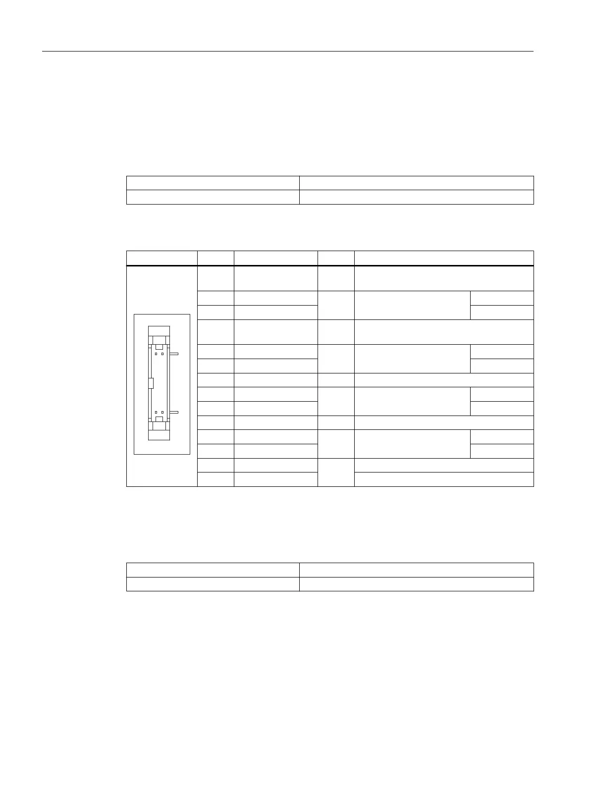
Table 5-5 Allocation of the LVDS display interface
Connector Pin Name Type Meaning
1/2 P5V_D_fused VO +5 V display supply voltage (fused in PCU/
TCU)
3 RXIN0-
O LVDS output signal
Bit 0 (-)
4 RXIN0+ Bit 0 (+)
5/6 P3V3_D_fused VO +3.3 V display supply voltage (fused in PCU/
TCU)
7 RXIN1-
O LVDS output signal
Bit 1 (-)
8 RXIN1+ Bit 1 (+)
9/10 GND - Ground
11 RXIN2-
O LVDS output signal
Bit 2 (-)
12 RXIN2+ Bit 2 (+)
13/14 GND - Ground
15 RXCLKIN-
O LVDS cycle clock signal
(-)
16 RXCLKIN+ (+)
17/18 GND
-
Ground
19/20 N.C. Not connected
LVDS display interface channel 2
Used for expanding the LVDS display interface channel 1 to control TFT displays with 1280 x
1024 pixels (SXGA).
Associated interface cable: K3
Connector type: 2 x 10-pin socket connector
Connection
5.1Pin assignment of the interfaces
TCU 30.3
36 Equipment Manual, 03/2023, A5E40874197B AD

 Loading...