Tool offsets
8.5 Activate 3D tool offsets (CUT3DC..., CUT3DF...)
Job planning
8-18 Programming Manual, 03/2006 Edition, 6FC5398-2BP10-1BA0
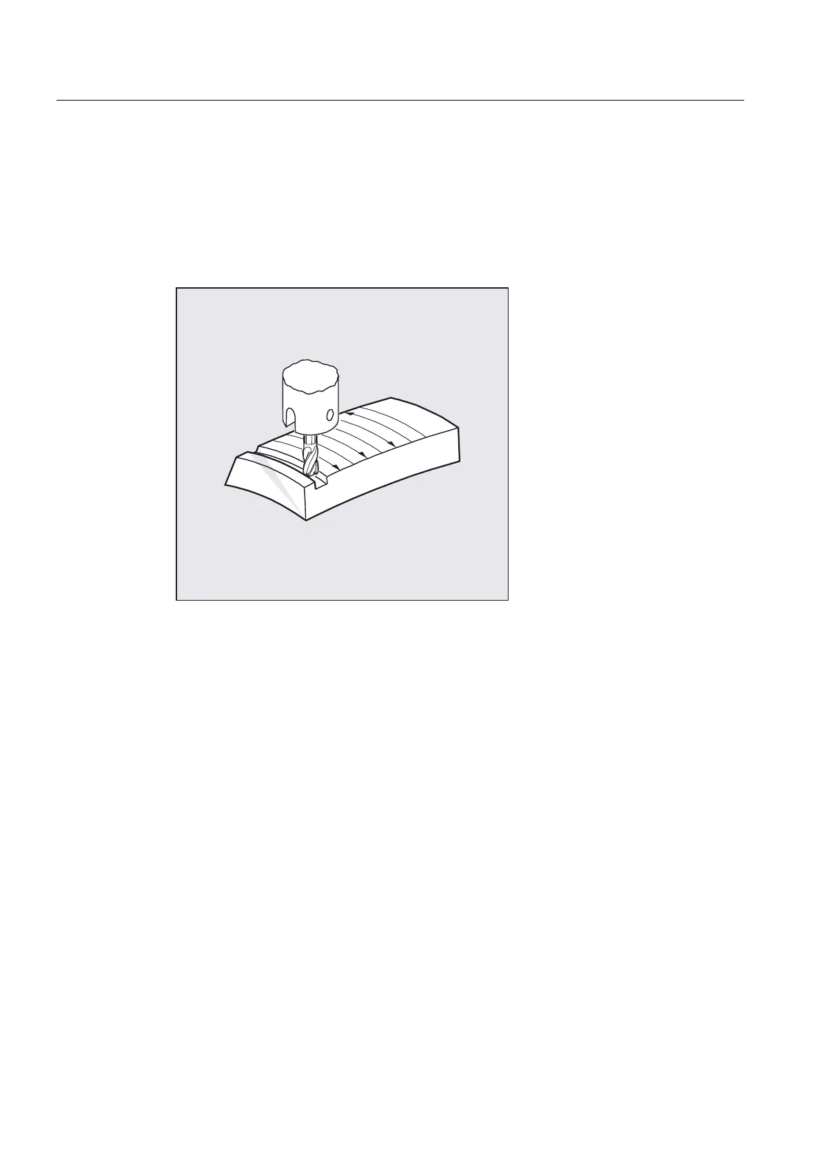
Face milling
For this type of 3D milling, you require line-by-line definition of 3D paths on the workpiece
surface. The tool shape and dimensions are taken into account in the calculations that are
normally performed in CAM. In addition to the NC blocks, the postprocessor writes the tool
orientations (when five-axis transformation is active) and the G code for the desired 3D tool
offset into the parts program. This feature offers the machine operator the option of using
slightly smaller tools than that used to calculate the NC paths.
Example:
NC blocks have been calculated with a 10 mm mill. In this case, the workpiece could also be
machined with a mill diameter of 9.9 mm, although this would result in a different surface
profile.

 Loading...


