Functions
2.9 Backup Time Overcurrent Protection
SIPROTEC, 7SD610, Manual
C53000-G1176-C145-6, Release date 02.2011
108
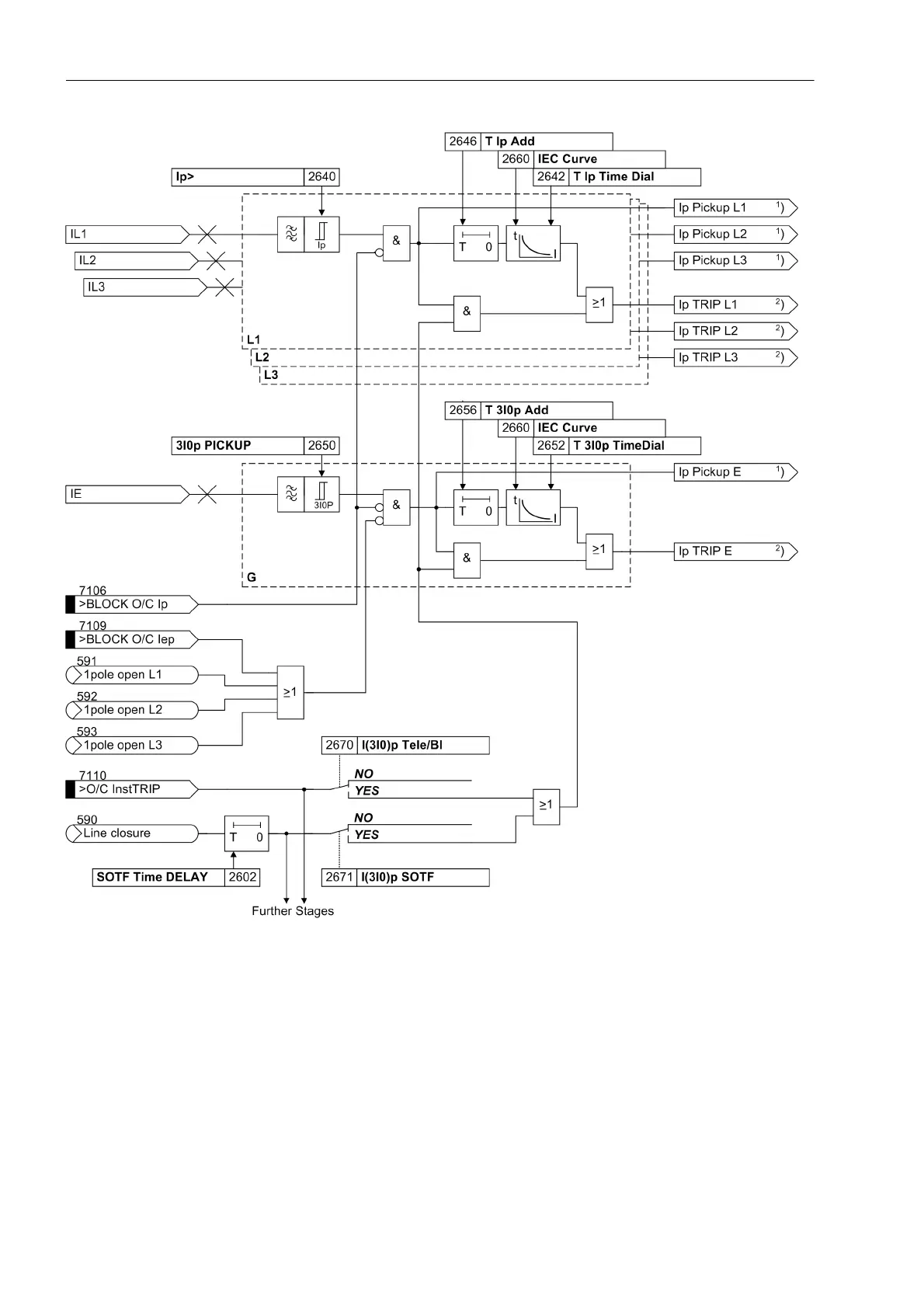
Figure 2-42 Logic diagram of the I
P
stage (inverse time overcurrent protection) - example of IEC curve
1
) Output indications associated with the pickup signals are listed in Table 2-3
2
) Output indications associated with the trip signals are listed in Table 2-4

 Loading...


