Technical Data
4.14 Monitoring Functions
SIPROTEC, 7SD610, Manual
C53000-G1176-C145-6, Release date 02.2011
359
4.14 Monitoring Functions
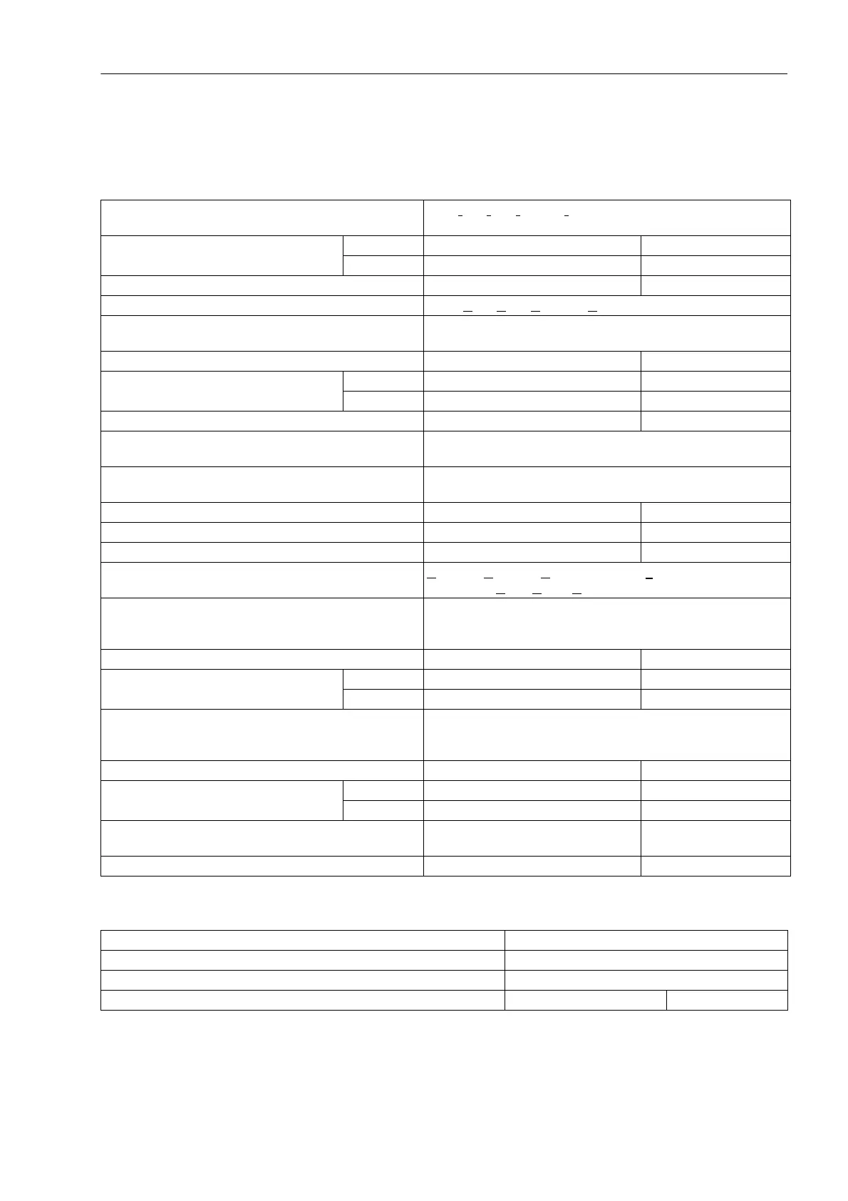
Measured Values
Trip Circuit Monitoring
Current sum I
F
= | I
L1
+ I
L2
+ I
L3
+ k
I
· I
E
| >
SUM.I Threshold · I
N
+ SUM. IFACTOR ·Σ | I |
- SUM.ILimit for I
N
= 1 A 0.10 A to 2.00 A Increment 0.01 A
for I
N
= 5 A 0.50 A to 10.00 A Increment 0.01 A
- SUM. I FACTOR 0.00 to 0.95 Increment 0.01
Voltage sum U
F
= | U
L1
+ U
L2
+ U
L3
+ k
U
· U
EN
| > 25 V
Current Symmetry | I
min
|/| I
max
| < BAL.FACTOR.I
as long as I
max
/I
N
> BAL.ILIMIT/I
N
- BAL.FACTOR.I 0.10 to 0.95 Increment 0.01
- BAL.ILIMIT for I
N
= 1 A 0.10 A to 1.00 A Increment 0.01 A
for I
N
= 5 A 0.50 A to 5.00 A Increment 0.01 A
- T BAL.ILIMIT 5 s to 100 s Increments 1 s
Broken wire monitoring of current transformer circuits on current step change
without voltage step change
Voltage balance | U
min
|/| U
max
| < BAL.FACTOR.U
as long as | U
max
| > BAL.ULIMIT
- BAL.FACTOR.U 0.58 to 0.95 Increment 0.01
- BAL.ULIMIT 10 V to 100 V Increment 1 V
- T BAL.ULIMIT 5 s to 100 s Increments 1 s
Voltage phase sequence U
L1
leads U
L2
leads U
L3
as long as | U
L1
|, | U
L2
| , | U
L3
| > 40 V/v3
Asymmetrical measuring voltage failure
(Fuse Failure Monitor)
3 · U
0
> FFM U> OR 3 · U
2
> FFM U>
AND simultaneously
3 · I
0
< FFM I< AND 3 · I
2
< FFM I<
- FFM U> 10 V to 100 V Increments 1 V
- FFM I<for I
N
= 1 A 0.10 A to 1.00 A Increment 0.01 A
for I
N
= 5 A 0.50 A to 5.00 A Increment 0.01 A
Three-phase measuring voltage failure
(Fuse Failure Monitor)
all U
Ph-E
< FFM UMEAS <
AND simultaneously
all ΔI
Ph
< FFM I
delta
- FFM UMEAS < 2 V to 100 V Increments 1 V
- FFM I
delta
for I
N
= 1 A 0.05 A to 1.00 A Increment 0.01 A
for I
N
= 5 A 0.25 A to 5.00 A Increment 0.01 A
- T V SUPERVISION (waiting time for additional
measured voltage failure monitoring)
0.00 s to 30.00 s Increments 0.01 s
- T mcb 0 ms to 30 ms Increments 1 ms
Number of supervised trip circuits 1 to 3
Operation of each trip circuit With 1 binary input or with 2 binary inputs
Pickup and dropout time Approx. 1 to 2 s
Settable delay time for operation with 1 binary input 1 s to 30 s Increments 1 s

 Loading...


