Functions
2.15 Monitoring Functions
SIPROTEC, 7SD610, Manual
C53000-G1176-C145-6, Release date 02.2011
218
2.15.2 Trip Circuit Supervision
The line protection 7SD610 is equipped with an integrated trip circuit supervision function. Depending on the
number of available binary inputs (not connected to a common potential), supervision with one or two binary
inputs can be selected. If the routing of the binary inputs required for this does not comply with the selected
supervision mode, an alarm is given („TripC1 ProgFAIL ...“, with identification of the non-compliant circuit).
When using two binary inputs, malfunctions in the trip circuit can be detected under all circuit breaker condi-
tions. When only one binary input is used, malfunctions in the circuit breaker itself cannot be detected. If single-
pole tripping is possible, a separate trip circuit supervision can be implemented for each circuit breaker pole
provided the required binary inputs are available.
2.15.2.1 Function Description
Supervision with Two Binary Inputs
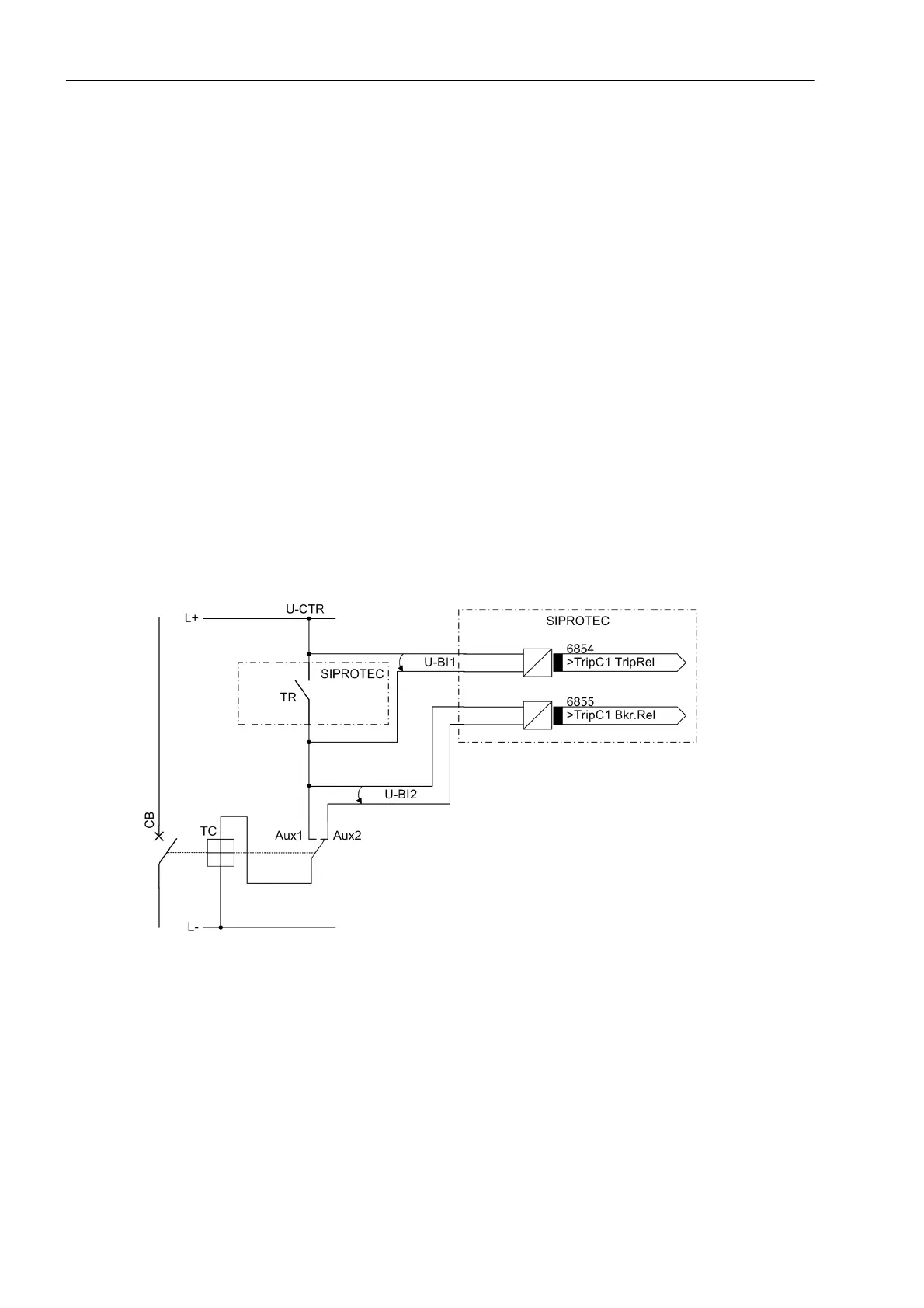
When using two binary inputs, these are connected according to Figure 2-95 parallel to the associated trip
contact on one side, and parallel to the circuit breaker auxiliary contacts on the other.
A precondition for the use of the trip circuit supervision is that the control voltage for the circuit breaker is higher
than the total of the minimum voltages drops at the two binary inputs (U
Ctrl
> 2·U
BImin
). Since at least 19 V are
needed for each binary input, the supervision function can only be used with a system control voltage of over
38 V.
Figure 2-95 Principle of the trip circuit supervision with two binary inputs
TR Trip relay contact
CB Circuit breaker
TC Circuit breaker trip coil
Aux1 Circuit breaker auxiliary contact (NO contact)
Aux2 Circuit breaker auxiliary contact (NC contact)
U-CTR Control voltage (trip voltage)
U-BI1 Input voltage of 1st binary input
U-BI2 Input voltage of 2nd binary input

 Loading...


