Functions
2.9 Backup Time Overcurrent Protection
SIPROTEC, 7SD610, Manual
C53000-G1176-C145-6, Release date 02.2011
110
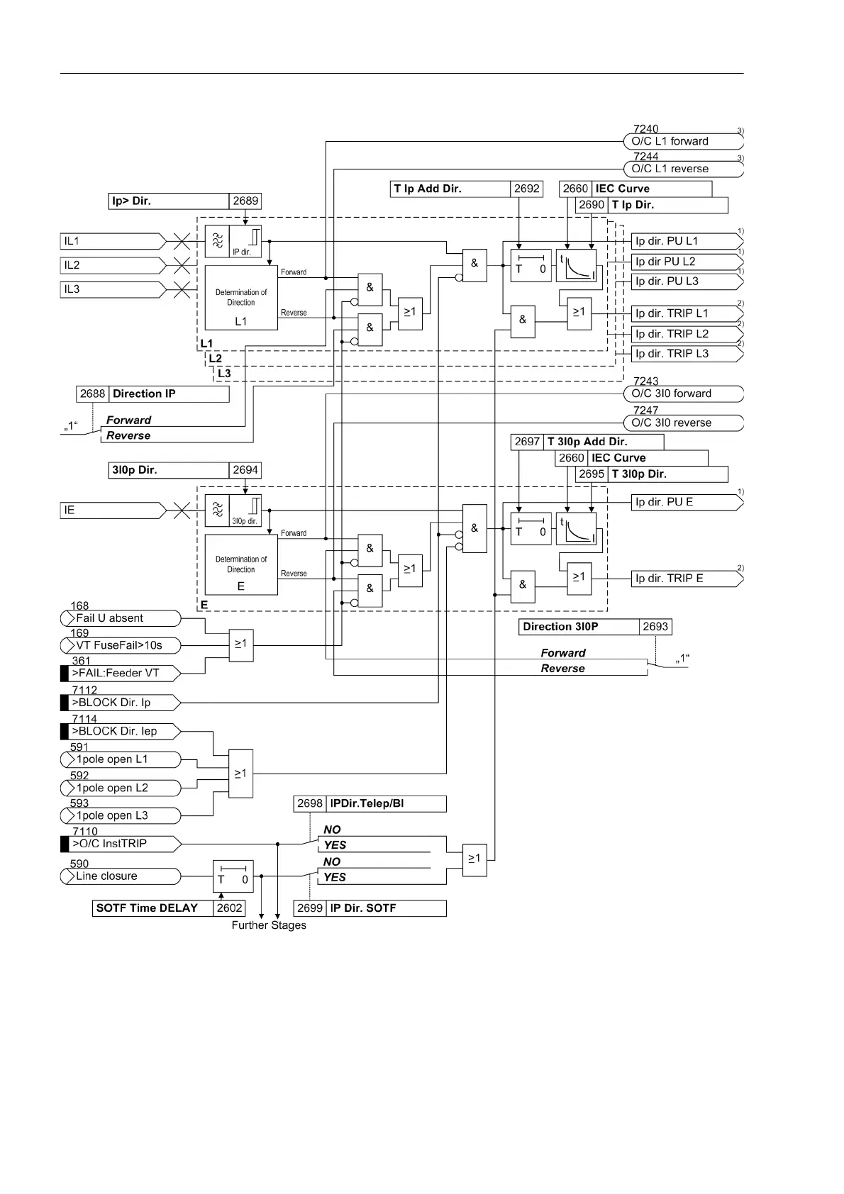
Figure 2-43 Logic diagram of the I
P
stage (directional, inverse time overcurrent protection), for example IEC character-
istics
1
) Output indications associated with the pickup signals are listed in Table 2-3
2
) Output indications associated with the trip signals are listed in Table 2-4
3
) The indications „O/C L2 forward“, „O/C L3 forward“, „O/C L2 reverse“, „O/C L3 reverse“ have
not been represented in the Figure, however, they are reported if necessary.

 Loading...


