Functions
2.13 Circuit Breaker Failure Protection
SIPROTEC, 7SD610, Manual
C53000-G1176-C145-6, Release date 02.2011
191
Note
If the circuit breaker failure protection shall perform a 1-pole TRIP repetition, the time set at the AR, address
3408 T-Start MONITOR, must be longer than the time parameterized for address 3903 1p-RETRIP (T1)
to prevent a 3-pole coupling by the AR before expiry of T1.
In order to prevent an AR after „BF T2-TRIP(bus)“, the time 3408 T-Start MONITOR can be set in such
a way that it expires simultaneously with T2 .
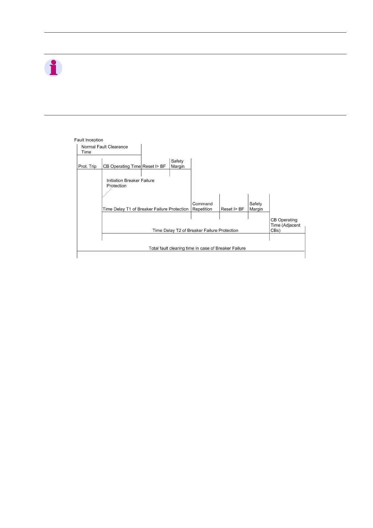
Figure 2-80 Time sequence example for normal clearance of a fault, and with circuit breaker failure, using
two-stage breaker failure protection
Single-stage circuit breaker failure protection
With single-stage operation, the adjacent circuit breakers (i.e. the circuit breakers of the busbar zone and, if
applicable, the circuit breaker at the remote end) are tripped after a delay time T2 (address 3906) should the
fault not have been cleared within this time.
The timers T1-1pole (address 3904) and T1-3pole (address 3905) are then set to ∞ since they are not
needed.
You can also use the first stage alone if you wish to use different delay times after 1-pole and 3-pole tripping of
the feeder protection. In this case set T1-1pole (address 3904) and T1-3pole (address 3905) separately,
but address 3903 1p-RETRIP (T1) to NO to avoid a 1-pole trip command to the busbar. Set T2 (address
3906) to ∞ or equal to T1-3pole (address 3905). Be sure that the correct trip commands are assigned to the
desired trip relay(s).
The delay time is determined from the maximum operating time of the feeder circuit breaker, the reset time of
the current detectors of the circuit breaker failure protection, plus a safety margin which allows for any tolerance
of the delay timers. The time sequence is illustrated in Figure 2-81. The dropout time for sinusoidal currents is
≤ 15 ms. If current transformer saturation is anticipated, the time should be set to 25 ms.

 Loading...


