Functions
2.15 Monitoring Functions
SIPROTEC, 7SD610, Manual
C53000-G1176-C145-6, Release date 02.2011
211
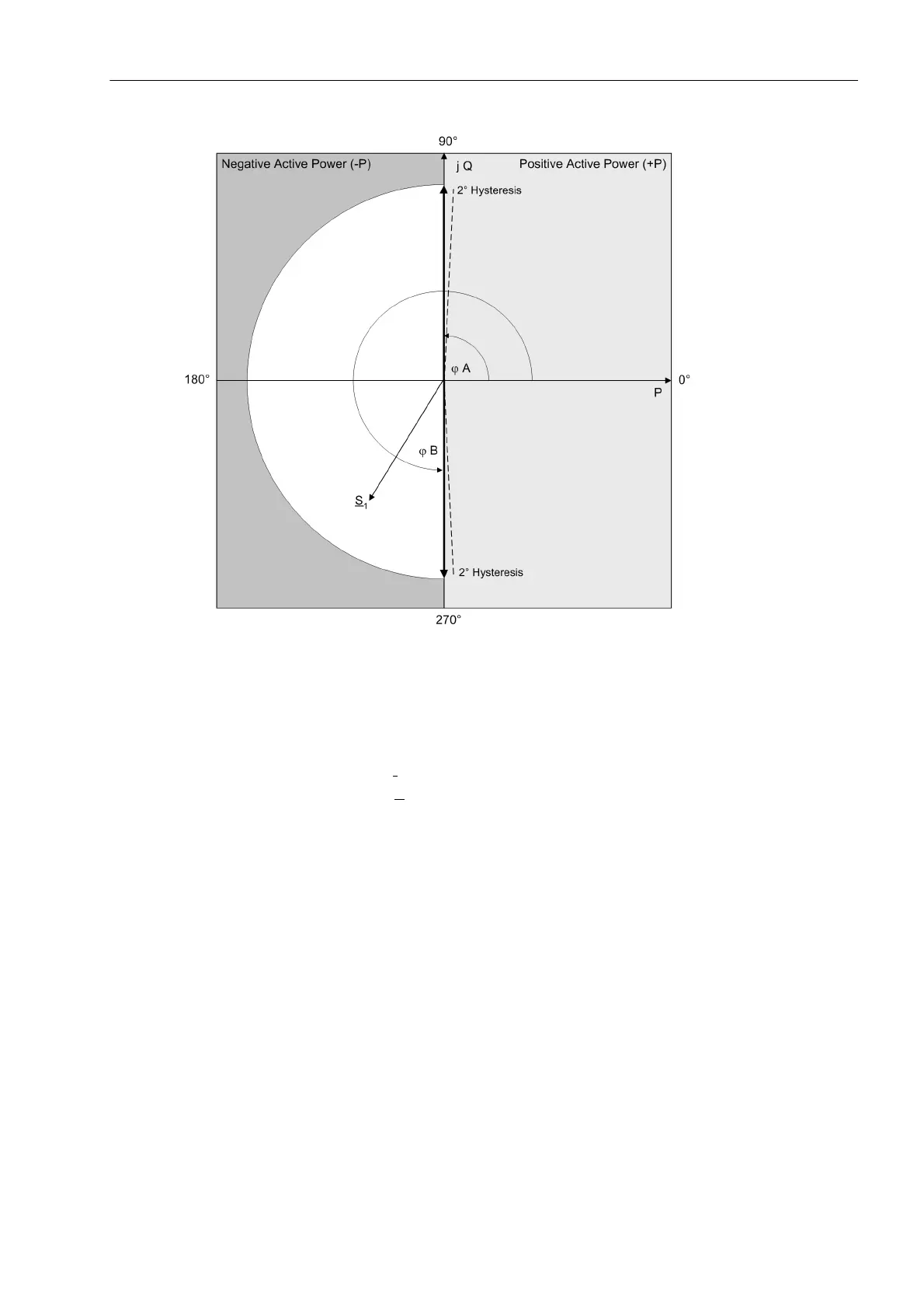
Figure 2-93 Phase Angle Monitoring for Negative Active Power
The two angles must be at least 3° apart; if they are not, monitoring is blocked, and the indication „ϕ Set
wrong“ (No. 132) is output.
The following conditions must be fulfilled for measurement to be enabled:
• The positive sequence current I
1
is higher than the value set in parameter 2943 I1>.
• The positive sequence voltage U
1
is higher than the value set in parameter 2944 U1>.
• The angles set in address 2941 ϕA and 2942 ϕB must be at least 3° apart. Incorrect parameter settings
cause the indication 132 „ϕ Set wrong“ to be output.
• The „Fuse-Failure-Monitor“ and the measured voltage failure monitoring must not have responded, and
binary input indication 361 „>FAIL:Feeder VT“ must not be present.
If monitoring is not active, this fact is signaled by the indication „ϕ(PQ Pos) block“ (No. 131).
Figure 2-94 shows the logic of the positive sequence system phase angle monitoring.

 Loading...


